The goal of our project was to create a persistence-of-vision (POV) analog clock using an LED display. The clock has a visual alarm system which lights up the entire display for two seconds if it reaches an alarm time. The current time and alarm times are preset into the clock before it begins to spin. Once the times are set, the clock spins up to a very stable speed, where small interferences will not disrupt the rotation of the clock. Once at max speed, the clock pulses LEDs to create a persistent display of the current time.
High Level Design
The basic premise of the POV display is that you pulse the LEDs such that on each revolution they are flashing in the exact same location. If this is happening fast enough, the human eye cannot detect the down time between flashes, and will see it as the LEDs being constantly on in one location. In order to achieve this, we determined that the LEDs needed to blink in the same location at least ten times per second to appear persistent. In order to achieve this speed, we were able to get the stepper motor to step every 4 ms. Each step of the motor is 7.5 degrees, so it requires 48 steps to complete one full rotation. This means that it takes 4*48 = 192 ms per revolution. This translates to 5.21 revolutions per second. This was only half the speed we needed, so we put a row of LEDs on either end of the spinning blade, effectively doubling the frequency of the LED flashing, since we could flash twice per revolution. This increased the frequency to 10.42 flashes per second, which was sufficient to achieve persistence of vision.
In order to ensure that the LEDs are flashing in the exact same location each revolution, we connected a photodiode to the underside of the spinning blade. This photodiode detects a line of IR LEDs that are fixed to the table. Each revolution, the clock is set relative to the fixed LEDs, with 12 o�clock located at the LEDs. This prevents any phasing in the display caused by compounding of errors, since any error is corrected each revolution. The photodiode/LED system also recalculates the period every revolution. This is used to adjust for any slight variations in the motor speed.
The basis for the alarm clock is simple. If the current time equals the alarm time, the full display is lit for two seconds. After these two seconds, the clock returns to ticking normally (it does not miss two seconds while the alarm is on).
Hardware Design
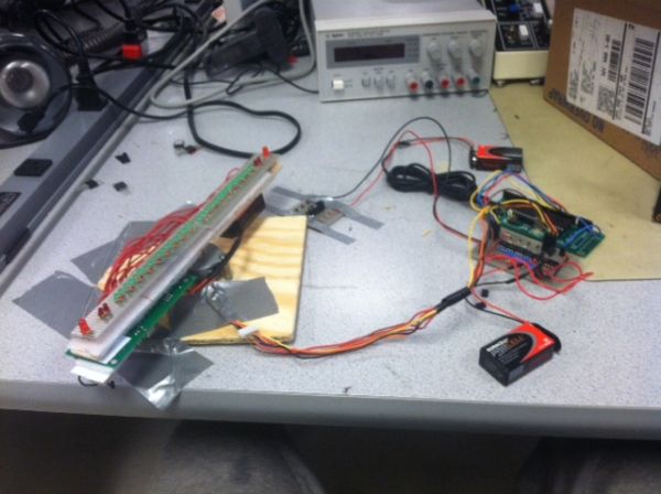
LED Display
The design of the LED display was made more difficult by the fact that we only had 5V of power out of the MCU to power the LEDs. Because of this, we could only put two LEDs and a resistor (to prevent the LEDs from burning out) in series while still achieving satisfactory brightness. This meant that we needed nine pairs of green LEDs, a pair of red LEDs, and one large red LED on each side of the blade. Each pair of LEDs (and the large red LED individually) was powered by its own pin in the MCU and was turned on by simply setting that port high. While this required many more MCU pins and more switching in the software, it also gave us more control of the display by allowing us to control smaller elements. This control could be used to create more intricate displays for alarms, or other non-clock related displays.
Photodiode/IR LED system
The photodiode/IR LED system is very straightforward. Normally, the voltage at D2 is high, since the unlit photodiode acts as an open circuit. As the photodiode passes above the IR LEDs, the photodiode become a closed circuit, and pulls the voltage at D2 to ground. Once the photodiode is passed the IR LEDs, the voltage at D2 goes back to high. This rising edge is then used by the MCU to trigger the interrupt that sets the 12 o�clock location and the tick distances.
The IR LEDs are continuously powered, and are each in series with a resistor to prevent them from burning out.
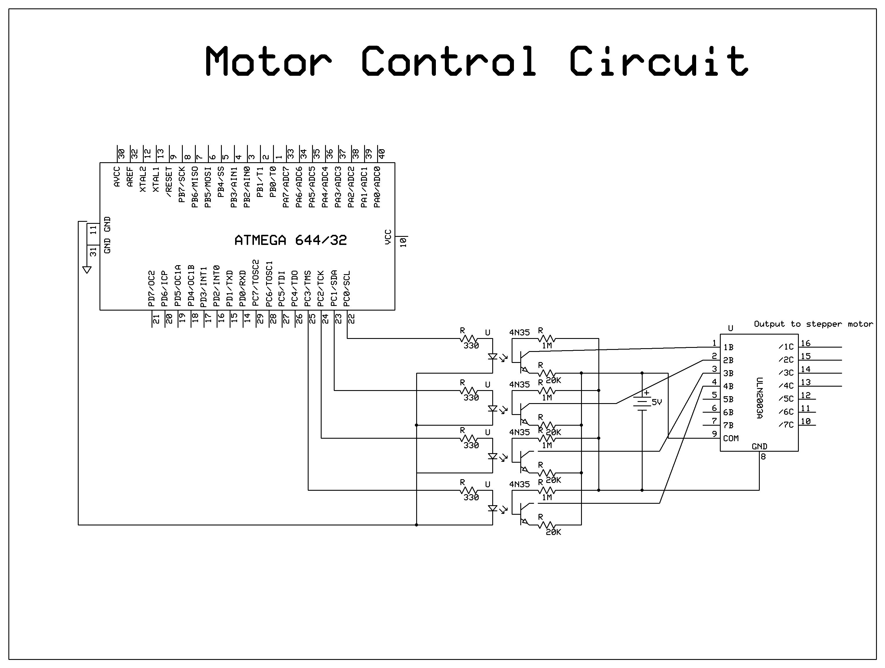
Stepper Motor Driver
The inductors are set so that Vcc is constantly applied to the center of each inductor, and you can control the flow of current by grounding either side. To control this grounding, the end of each inductor is connected to ground across a transistor. The four transistors necessary for this are contained within the ULN2003 chip. The voltage on the gate of these transistors is connected to photodiodes, which are controlled by LEDs connected to four separate pins on the MCU. Each pair of photodiode and LED is contained within a single 4N35 chip. When a pin is set high, it turns on the LED which in turn allows current to flow through the photodiode, this changes the voltage on the gate of the transistor and allows current to flow between the drain and source, grounding the end of the inductor. This process is controlled by software so that the inductors are set in such a way that the magnetic fields pull the magnet in a circle.
The inductors are set so that Vcc is constantly applied to the center of each inductor, and you can control the flow of current by grounding either side. To control this grounding, the end of each inductor is connected to ground across a transistor. The voltage on the gate of these transistors is connected to photodiodes, which is controlled by LEDs connected to four separate pins on the MCU. When a pin is set high, it turns on the LED which in turn allows current to flow through the photodiode, this changes the voltage on the gate of the transistor and allows current to flow between the drain and source, grounding the end of the inductor. This process is controlled by software so that the inductors are set in such a way that the magnetic fields pull the magnet in a circle.
Parts List:
| Part Description | Unit Cost | Quantity | Vendor | Total Cost |
|---|---|---|---|---|
| Green LED | $0.04 | 36 | Lab Stock | $1.44 |
| Red LED | $0.04 | 6 | Lab Stock | $0.24 |
| IR LED | $0.04 | 3 | Lab Stock | $0.12 |
| Phototransistor | $0.00 | 1 | Lab Stock | $0.00 |
| Battery Connector | $0.00 | 1 | Lab Stock | $0.00 |
| Velcro Strips | $5.00 | 1 | Walmart | $5.00 |
| 9V Battery | $1.42 | 1 | Amazon | $1.42 |
| Salvaged Atmega 1284P | $0.00 | 1 | Lab Stock | $0.00 |
| Salvaged Atmega 644 | $0.00 | 1 | Lab Stock | $0.00 |
| Stepper Motor | $0.00 | 1 | Lab Stock | $0.00 |
| Wood Piece | $0.00 | 1 | Lab Stock | $0.00 |
| Solder Board | $2.50 | 1 | Lab Stock | $5.00 |
| Header Pins | $0.05 | 82 | Lab Stock | $4.10 |
| 330 Ohm R | $0.00 | 29 | Lab Stock | $0.00 |
| 20k Ohm R | $0.00 | 5 | Lab Stock | $0.00 |
| 1M Ohm R | $0.00 | 4 | Lab Stock | $0.00 |
| 4N35 Chip | $0.50 | 4 | Lab Stock | $2.00 |
| ULN2003 Chip | $0.50 | 1 | Lab Stock | $0.50 |
| Wire | $0.00 | 15′ | Lab Stock | $0.00 |
| Total | $19.82 |
For more detail: Persistance of Vision Clock Using Atmega644