Summary of Pololu USB AVR Programmer User’s Guide
The Pololu USB AVR Programmer is a second-generation tool for programming Atmel AVR microcontrollers, emulating an STK500 interface. It features a TTL serial port and SLO-scope for debugging, supported by Windows, Linux, and limited Mac OS X drivers. The device includes specific LEDs for status monitoring and connects via USB to target boards like Orangutan controllers and the 3pi robot.
Parts used in the Pololu USB AVR Programmer:
- USB A to mini-B cable
- 6-pin ISP programming cable
- Green LED
- Yellow LED
- Red LED
- VBUS line
- GND line
- TX and RX lines
- A and B lines
- Standard 6-pin AVR ISP connector
Overview
The Pololu USB AVR programmer [http://www.pololu.com/product/1300] is a programmer for Atmel’s AVR
microcontrollers and controller boards based on these MCUs, such as Pololu Orangutan robot controllers
[http://www.pololu.com/category/8/robot-controllers] and the 3pi robot [http://www.pololu.com/product/975]. The programmer emulates an STK500 on a virtual serial port, making it compatible with standard AVR programming software. Two additional features help with building and debugging projects: a TTL-level serial port for general-purpose communication and a SLO-scope for monitoring signals and voltage levels.
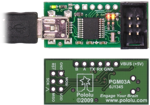
Please note that this guide applies to Pololu’s second-generation AVR programmer (pictured to the left below), not
the original, similar-looking Orangutan USB programmer [http://www.pololu.com/product/740] (pictured to the right).
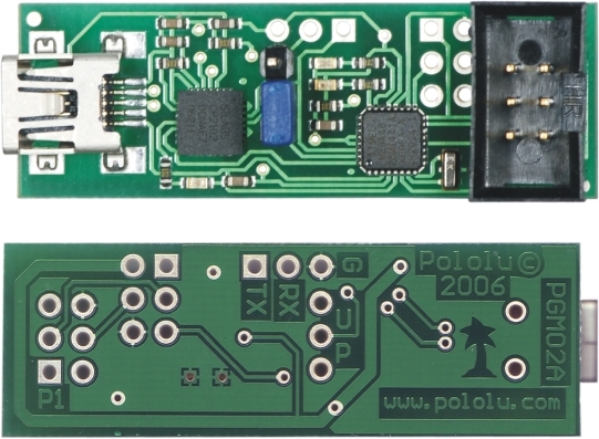
If you have the original Orangutan USB programmer, you can find it’s user’s guide here [http://www.pololu.com/docs/
0J6].
Important Safety Warning and Handling Procedures
The USB AVR programmer is not intended for young children! Younger users should use this product only under
adult supervision. By using this product, you agree not to hold Pololu liable for any injury or damage related to the
use or to the performance of this product. This product is not designed for, and should not be used in, applications
where the malfunction of the product could cause injury or damage. Please take note of these additional precautions:
• The USB AVR programmer contains lead, so follow appropriate handling procedures, such as washing hands
after handling.
• Since the PCB and its components are exposed, take standard precautions to protect your programmer from
ESD (electrostatic discharge), such as first touching the surface the programmer is resting on before picking
it up. When handing the programmer to another person, first touch their hand with your hand to equalize any
charge imbalance between you so that you don’t discharge through the programmer as the exchange is made.
1.a. Module Pinout and Components
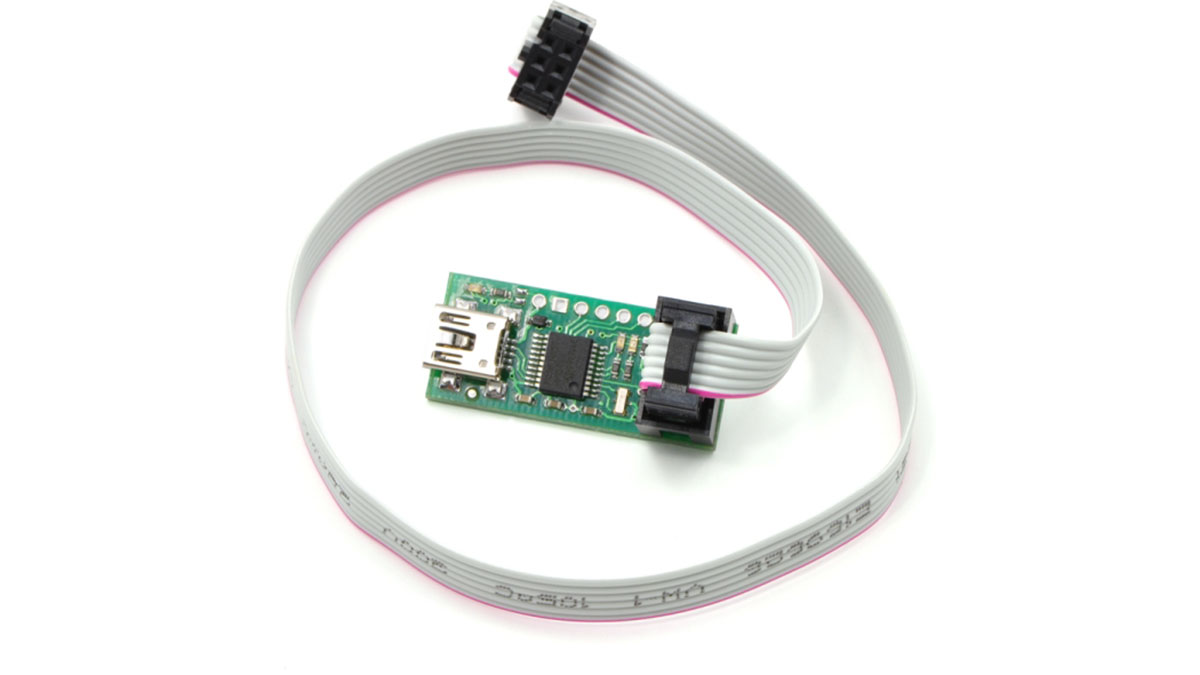
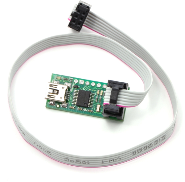
The Pololu USB AVR programmer connects to a computer’s USB port via an included USB A to mini-B cable
[http://www.pololu.com/product/1129], and it connects to the target device via an included 6-pin ISP programming cable
[http://www.pololu.com/product/972] (the older, 10-pin ISP connections are not directly supported, but it is easy to create
or purchase a 6-pin-to-10-pin ISP adapter).
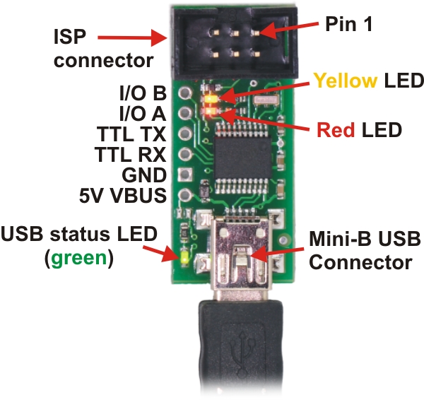
The USB AVR programmer has three indicator LEDs:
• The green LED indicates the USB status of the device. When you connect the programmer to the computer
via the USB cable, the green LED will start blinking slowly. The blinking continues until it receives a particular
message from the computer indicating that the drivers are installed correctly. After the programmer gets this
message, the green LED will be on, but it will flicker briefly when there is USB activity.
• The yellow LED indicates that the programmer is doing something. When it is blinking, it means that the
programmer has detected the target device (the voltage on the target VDD line is high). When it is on solid, it
means that the SLO-scope is enabled, and lines A and B are used for the SLO-scope instead of the USB-to-TTLserial adapter.
• The red LED indicates an error or warning. When it is blinking, it means that the target device is not detected
(the voltage on the target VDD line is low). When it is on solid, it means that the last attempt at programming
resulted in an error. You can determine the source of the error by running the configuration utility (see Section
3.e).
The VBUS line provides direct access to the 5V VBUS line on the USB cable and can be used to power additional
devices. The line can provide up to 100 mA, so the current draw of your programmer plus any additional devices
should not exceed this amount. If you attempt to draw more than this limit, your computer might disconnect the USB
port temporarily or take other actions to limit the use of USB power.
The GND line provides direct access to the grounded line on the USB cable (and ground on the programmer).
The TX and RX lines are the TTL serial port for the USB-to-TTL-serial adapter. They are labeled from the computer’s
perspective: TX is an output that connects to your target’s serial receive pin and RX is an input that connects to your
target’s serial transmit pin. Section 6 describes how to use these lines to communicate with your devices from the
computer.
The A and B lines can be used as serial control/handshaking lines for the USB-to-TTL-serial adapter (see Section
6.a) or as analog voltage inputs for the SLO-scope (see Section 7).
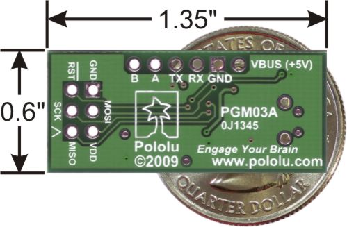
The USB AVR programmer has a standard 6-pin AVR ISP connector for programming AVRs, and the pins are
labeled on the silkscreen on the bottom side of the board. The pins on the connector are:
- MISO: The “Master Input, Slave Output” line for SPI communication with the target AVR. The programmer
is the master, so this line is an input. - VDD: An input line that the programmer uses to measure the voltage of the target AVR. While programming
the target device, the programmer uses this line to constantly monitor the target VDD. If the voltage goes
too low or varies too much, then the programmer aborts programming in order to avoid damage to the target
AVR. Section 3.e has more information about target VDD monitoring. The VDD line is not used to power the
programmer; the programmer is powered from the USB. This line cannot be used to power the target device; the
target device must be independently powered for programming to work. - SCK: The clock line for SPI communication with the target AVR. The programmer is the master, so this line
is an output during programming. - MOSI: The “Master Output, Slave Input” line for SPI communication with the target AVR. The programmer
is the master, so this line is an output during programming. - RST: The target AVR’s reset line. This line is used as an output driven low during programming to hold the
AVR in reset. - GND: Ground. This line should be connected to the target device’s ground.
1.b. Supported Microcontrollers
The programmer should work with all AVRs that can be programmed with the AVR ISP interface, but it has not
been tested on all devices. It has been tested with all Orangutan robot controllers [http://www.pololu.com/category/8/
robot-controllers] and the 3pi Robot [http://www.pololu.com/product/975]. The programmer features upgradable firmware,
allowing updates for future devices. It does not currently work with Atmel’s XMega line of microcontrollers.
The programmer is powered by the 5V USB power bus, and it is intended for programming AVRs that are running at
close to 5 V (note that the programmer does not deliver power to the target device).
1.c. Supported Operating Systems
The Pololu USB AVR programmer has been tested under Microsoft Windows XP (Service Pack 3), Windows Vista,
Windows 7, Windows 8, and Linux. See Section 5 for limited Mac OS X support.
The programmer’s configuration utility works only in Windows, but this should not be a big problem for Linux users
because all the options that can be set in the configuration utility are stored in persistent memory, so you would only
have to use Windows when you want to change those parameters, which should be rarely (if ever). The programmer
does not require the configuration to program AVRs or to use the TX and RX USB-to-TTL-serial adapter pins.
The SLO-scope application works only in Windows.
The programmer is compatible with a variety of AVR programming utilities for Windows, Linux and Mac OS,
including AVRDUDE, AVR Studio 4, AVR Studio 5, and Atmel Studio 6
Getting Started in Windows
The Pololu USB AVR programmer works in Windows XP, Windows Vista, and Windows 7.
3.a. Installing Windows Drivers and Software
Please note that these drivers will only work for the USB AVR programmer; if you have Pololu’s original Orangutan
USB programmer [http://www.pololu.com/product/740], you will need to install the drivers specific to that device.
Before you connect your Pololu USB AVR programmer to a computer running Microsoft Windows, you must install
its drivers:
- Download and install the Pololu AVR Development Bundle [http://www.pololu.com/file-redirect/avr-developmentbundle] (~11 MB exe). This includes the drivers and software for the Pololu USB AVR Programmer, along
with the Pololu AVR C/C++ Library and the Orangutan SVP Drivers. If you are not sure which of these
components you need, it is OK to install all of them. If you only need to install the drivers and software for
the programmer, you can download those separately: USB AVR Programmer Windows Drivers and Software
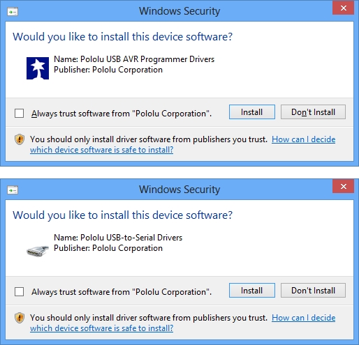
[http://www.pololu.com/file/download/pololu-usb-avr-programmer-win-121114.exe?file_id=0J486] (11MB exe). - During the installation, Windows will ask you if you want to install the drivers. Click “Install” (Windows 8,
7, and Vista) or “Continue Anyway” (Windows XP).
Windows 8, Windows 7, and Windows Vista users: After the installation has finished, your computer should
automatically install the necessary drivers when you connect a Pololu USB AVR programmer, in which case no
further action from you is required.
Windows XP users: After the installation has finished, follow steps 3-7 for each new Pololu USB AVR programmer
you connect to your computer.
- Connect the USB AVR programmer to your computer’s USB port. The programmer is actually three
devices in one so your XP computer will detect all three of those new devices and display the “Found New
Hardware Wizard” three times. Each time the “Found New Hardware Wizard” pops up, follow steps 4-7. - When the “Found New Hardware Wizard” is displayed, select “No, not this time” and click “Next”.
- On the second screen of the “Found New Hardware Wizard”, select “Install the software automatically” and
click “Next”.
Source: Pololu USB AVR Programmer User’s Guide
- What is the Pololu USB AVR programmer?
It is a programmer for Atmel's AVR microcontrollers that emulates an STK500 on a virtual serial port. - How do I install drivers for Windows XP?
You must download and install the Pololu AVR Development Bundle or separate drivers before connecting the device. - Does the programmer power the target device?
No, the target device must be independently powered as the VDD line only monitors voltage. - Can this programmer work with XMega microcontrollers?
No, it does not currently work with Atmel's XMega line of microcontrollers. - What operating systems are supported?
It has been tested under Windows XP through 8 and Linux, with limited Mac OS X support. - How many devices does Windows XP detect upon connection?
Windows XP will detect three new devices because the programmer functions as three devices in one. - What does the red LED indicate?
A blinking red LED means the target device is not detected, while a solid red LED indicates a programming error. - Can I use the A and B lines for other purposes?
Yes, they can be used as serial control/handshaking lines or as analog voltage inputs for the SLO-scope.