
Summary of POV Magic 8 Ball Using Atmega1284
In our ECE 4760 final project we built a voice-controlled magic 8 ball using a rotating persistence-of-vision (POV) display. Users speak yes/no questions; an infrared link transmits commands to a rotating PCB with LEDs, MCU, speed sensing, and battery. A stepper motor spins the semi-circular LED array at about 10 RPS to form a spherical display by timing LED on/off durations. Key work included mechanical supports, motor drive hardware, isolation between MCU and drivers, and software to map a 19×90 pixel matrix for the POV display.
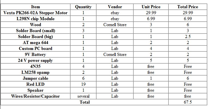
Parts used in the POV Magic 8 Ball:
- Vexta PK266-02A stepper motor
- L298N H-bridge driver
- 4N35 optocouplers
- Atmega1284 MCU (rotating board MCU and base MCU)
- Infrared emitter(s) (on non-rotating frame)
- Infrared receiver(s) (on rotating PCB)
- Series of semi-circle LEDs (19 LEDs)
- Battery (for rotating PCB)
- 24 V 2 A power supply
- Wood support pieces and shafts for mechanical mounting
- Rotating PCB with speed measurement circuit
1.Introduction
In our final project of ECE 4760, we designed a magic 8 ball, which is a rotating POV (persistence of vision) display controlled by voice commands. In our design, users can ask yes/no based questions via a small speaker, and the rotating POV part can display random answer of yes or no to answer that the question. The system works just as the traditional magic 8 ball, with the answer displaying on a sphere created by a series of rotating LEDs and using the persistence of vision mechanism.
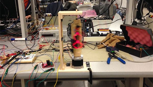
A persistence of vision (POV) refers to the phenomenon of the human eye in which an afterimage exists for a brief time (10 ms). A POV display exploits this phenomena by spinning a one dimensional row of LED’s through a two dimensional space at such a high frequency that a two dimensional display is visible. In our case, we created a sphere display by spinning semi-circle shaped LEDs around a central motor shaft. The rotational speed of the LED’s is fast enough such that the human eye perceives a two dimensional image.
The overall design of this project can be grouped in the following three categories: circuit design, mechanical design, and software design. The most labor intensive portion of this project was the mechanical design and the circuit design. The circuit schematics and software design should be integrated on the frame work of mechanical structure, which is the most challenging part of our design implementation.
2.High Level Design
The original idea of our project came from a very popular American sitcom in the 90s – Friends. In this show, we saw the magic 8 ball for the very first time, and were amused by Ross asking it whether he should see Rachel again. Being a huge fan of Friends and attracted to the idea of asking questions to a magic ball to make complicated decisions, we decided to build our electrical version of magic 8 ball, with which people ask questions via a small speaker to the ball and get random answer displayed automatically.
The next step of our design was a series of brainstorming to decide how the answer would be displayed. In our first scheme, a plastic ball with a LCD screen embedded in it would be responsible for displaying answers. A stepper motor would drive the plastic ball to spin when people starts to ask questions and stop after people finishing the questions. In other words, our first scheme is about voice commanding the motor spin or stop, while LCD display random answer when motor stops. After a series of further discussion, we quickly drop this scheme because we met several folds of skill limitation. First, it is hard to embed a LCD screen to an integral plastic ball and fix a microcontroller in such as small area. Second, it is also hard to synchronize the motor and the LCD display, which means no good ways to tell the ball when to display random answer if no electric components like a speed sensor or a displacement sensor are employed to the system. To simply our design, we gave up our first design scheme and adopted another display scheme, the POV display.
Using POV display helps us avoid several skill limitation mentioned above. First, we don’t need an entity version of ball to do the display. Instead, we only need a series of semi-circle shaped LEDs rotating in a central shaft to create the outline of the ball. Meanwhile, by lighting certain LEDs, we can create the vision of displaying figures on a spherical surface. Second, we don’t need to employ such speed sensor or displacement sensor as mentioned before, we only need an infrared emitter on the non-rotating frame to send voice commands, and an infrared receiver on the rotating part to receive commands. To fulfill these, we only need a circuit board to serve as the rotating part, on which a series of semi-circle shaped LEDs, speed measurement circuit, voice command receiver, a MCU and a battery are embedded. In order to be able to drive the rotating circuit board, we need a high-torque motor.
The POV display logic behind our project is very straightforward. Our software must calculate the rotations per second (RPS), and set the time duration to display each “pixel” of the display (explained in software section). From a high level design, we simply measure the period of each rotation, divide time the central shaft takes to rotate through that section by the number pixels we allow to display and then calculate the amount of time each pixel occupies during the rotation. By turning on a LED for just that duration of time, we can then display the pixel. There are 19 LEDs consisting of the semi-circle, and we define two degree as a pixel while figures are only allowed to display in 180 degree. Thus, we mapped the entire display area to a 19 by 90 matrix where each element in the matrix represents a pixel.
The nature of our design allows the software and hardware design to be relatively independent of each other in terms of tradeoffs. However, there do exist some cases in which hardware circuit design may affect the stability of our software. For example, we have two infrared receivers on our rotating circuit board: one to measure the speed and synchronize the display, another to receive voice commands to display corresponding figures on the spinning spherical surface. It is important that these two infrared emitter commands from non-rotating frame should only give commands to its corresponding receiver.
The system schematic diagram is shown in Figure 1. As we can see from the diagram, two MCU has different responsibilities and cooperate together to fulfill the entire function as a rotating POV display.
3. Design
3.1 Mechanical Design
Because we expect to rotate a serial of LED and display figures in spherical surface, we need to fix both side of the board containing the serial of LED (in case it shaking too heavily and affecting the receiving of infrared signal). Besides, we need to fix two IR transmitters, making the IR receivers on the rotating board receive a signal per revolution. So we build a wood support for our POV, both used to fixed the free end of the rotating board and to fix the IR transmitters.
We make two small pieces of woods with hole in it, and paste these two pieces of woods to both ends of the board containing the LED. One was connecting to the stepper motor, and the other was connecting to a shaft which going through a hole in the top board. One thing we need to make sure is that the shaft of the motor should be in the exactly same position with the top hole of the board and the shaft in the top. After doing these, we can guarantee the serial of LED can rotate smoothly and receive the signal from infrared.
3.2 Hardware Design
3.2.1 Motor
In our design, a motor is needed to drive the rotating part to spin at around 10 RPS to achieve the best performance of POV display. Because our rotating circuit board has a lot of electrical components embedded on, we need a motor which can generate high torque. Besides, we also need our motor to run at a constant speed, and if the load changes in a variable range, the motor should still hold the constant speed. In our design, we can choose between three types of motors: DC motor, AC motor, and a stepper motor.
Because of the current/torque relationship:

we cannot achieve very big speed changes due to torque limitation. In other words, in order to meet the criteria of torque generation to drive the rotating part, we have to slowly ramp up the motor speed. For an AC motor, we have to use a voltage adaptor to ramp up the input voltage, which means more hardware implemented. As for a DC motor, instead of using PID control, we can simply apply a constant DC voltage to achieve constant motor speed in condition of motor load not changing in a wide range. As usual, we also have to slowly ramp up the input DC voltage to meet the torque limitation. Both of the AC and DC motors require additional hardware (such as voltage adaptor or regulator) to achieve input voltage ramp up in order to slowly regulate the motor speed to rated value. So, we chose a stepper motor, which makes us able to ramp up speed only using software.
Stepper Motor Hardware Implementation
We chose Vexta PK266-02A stepper motor because it can generate the holding torque of up to 166 oz-in. Considering that our rotating part is quite heavy and torque consuming, we also need to use this stepper motor in bipolar mode, in which the coil is twice as the unipolar. And we also adopted 50% control signals overlap to maximum the torque output. When used in bipolar mode, the coil resistance for one phase is 4 ohms, and because the rated current for one phase is 2A, so we need at least 8V voltage input. With the speed of the motor increasing, the coil impedance also increases. So, we need more than 8V voltage input. After several trials, we found out that a 24 volts output voltage with 2A rated current power supply can drive our stepper motor to rotate at around 10 RPS.
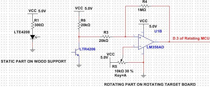
Another important issue about the hardware circuit implementation is about control circuit, drive circuit, and the isolation between them. Because we use the motor in bipolar mode, we need two H bridges for both phases of the coil. We chose L298N model (shown in Figure 4) as the H bridge drive-circuit in consideration that it can handle up to 2A emitter/collector current when switched on. And it can handle up to 36V collector-emitter voltage when switched off, which means it can be used in our 24 volts power supply. Note that the L298N model we bought has already had four freewheeling diodes connected in antiparallel with each phase of the inductive load, so we can safely use this model to drive a stepper motor and do not need to worry about no current return path for the motor coil when the H-bridge is switched off.
We used MCU C.0~C.3 port to output sequential control signals for two phase of our stepper motor. It is important to isolate this control circuit with the drive circuit of H bridge, because the drive circuit may draw up to 2A current and if this high current couple to MCU control circuit from common ground resistor, MCU pins may be destroyed. In our design, we use 4N35 to isolate the control and drive circuit. Note that 4N35 has the bandwidth limitation of 1K Hz, so the stepper motor has the speed limitation coming from the restriction of control signal frequency.
Parts List:
For more detail: POV Magic 8 Ball Using Atmega1284
- How does the POV Magic 8 Ball receive voice commands?
Voice commands are sent from the non-rotating frame via infrared emitters and received by infrared receivers on the rotating PCB. - What displays the yes or no answer?
A rotating semi-circle LED array on the rotating PCB forms a spherical POV display and lights pixels to show yes or no. - How is rotation speed measured for synchronization?
One infrared receiver on the rotating board measures the speed by receiving an IR pulse per revolution for synchronization. - Why was a stepper motor chosen?
A stepper motor was chosen for high torque, ability to ramp speed via software, and reliable constant-speed operation under load. - Which motor driver is used to drive the stepper motor?
The L298N H-bridge driver is used to drive the bipolar stepper motor phases. - How many LEDs and pixels are used in the display mapping?
There are 19 LEDs and the display is mapped to a 19 by 90 pixel matrix, using 2 degrees per pixel across 180 degrees. - How is isolation achieved between MCU control and motor drive?
4N35 optocouplers are used to isolate the MCU control signals from the high-current drive circuit. - What power supply was used to run the stepper motor?
A 24 volt, 2 amp power supply was used to drive the stepper motor to around 10 RPS.
