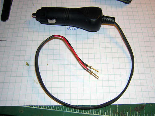
This instructuable will show you how to build your own vehicle-based regulated power supply that will power an Arduino or any AVRup to 5V. It’s an inexpensive and easy to build project that you can have up and going in no time, and additionally, with very few external components. This device makes use of your car’s cigarette lighter socket for power and then performs a DC/DC step-down to 5Vs while regulating the power.Go to the next step to get started!
Step 1 Bill of Material
What You’ll Need
As I mentioned in the intro, this project has very few requirements or external components. Here’s what you’ll need:
- Auto power plug (www.mouser.com #171-A1378-EX $2.33)
- 0.1uF 0805 capacitor (www.avnet.com #08051C103JAT2A $0.09)
- 0.33uF 0805 capacitor (www.avnet.com #0805YC33rKAT2A $0.04)
- 1uF 0805 capacitor (www.avnet.net #08053C105KAT2A $0.10)
- 5V regulator DPAK MC7805CD (www.avnet.com $0.22)
The PCB I designed can either be etched by you with your favorite PCB creation method, or alternatively, you may send the gerber files (which I include) off to a fab house, in my case, www.seeedstudio.com Fusion PCB service for professional fabrication on the cheap. I got 20 excellently produced boards for $10. Its really hard to beat, especially when you’re working with small SMD components, but it’s entirely possible to etch these boards yourself, if you’re so inclined.
Various Sundries
Besides the items mentioned above, you should have a soldering iron, solder, maybe some flux, tweezers, wire cutters, snippers, crimper, etc. But you probably already have this stuff laying around.
Turn the page to get started on the design.
Step 2 PCB Design
There is a small space within the auto power jack shown in step 2 that can fit a small PCB. And yes, I do mean small. The board should measure really no larger than 29mm x 10mm (although my board is exactly 29.21 x 10.16 mm). This size really screams for the use of SMD components. Luckily, we can use SMD packages that are small. But not too small for us to work with manually.
Overview
The design here is very simple and follows a standard linear power regulator setup. We take in the 12V or so from the car and pass it to a 5V linear regulator with a few capacitors attached to handle transients and unwanted frequencies, helping to reduce ripple voltage in the output. Finally, we output this regulated 5V through a set of wires that will connect to the Arduino or AVR board.
Schematics and Board
Check out the included pictures of the schematic and board to get an idea of how this is all setup. It’s very straight forward and shouldn’t offer too many surprises for those of you that have built your own power supplies for microcontrollers before. Also, find attached the actual schematic and board file (*.sch and *.brd) for use in Eagle, if you want to change or modify anything. Finally, if you do choose the option of having your board custom fabricated, I’ve also attached a zip file of the necessary files you will need to send to Seeedstudio to have them build the PCB. From time of order to the time I received my PCBs was about 2 weeks. Cheap and speedy.
For more Detail: Power Your Arduino From Your Car
