Gotta love microcontrollers.They do lots of stuff … you can find them in computer mice , traffic lights , toys , and almost all electronic devices nowadays.
Well , this is a project that pushes an 8-bit ATMega32 microcontroller to the limits.
As you guessed from the title , it is a game system. Here are some of the specifications :
*27MHz overclocked (from 16MHz) AVR ATmega32 microcontroller , with 32KB flash , 2KB RAM.I think you can also use an ATMega644.They have the same pinouts.I personally haven’t tried with an atmega644.
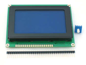
*128×64 monochrome KS0108 based display
*4 Voice sound engine : (Sounds the same as the NES)
*2 Variable volume square wave channels.
*1 DDS (Direct Digital Synthesis) Wave table channel with fixed volume , that can play : Sine waves , Triangle waves , Sawtooth waves , Square waves , or any other simple waveform.
*1 DDS White noise channel (Basically the same as the first wave table channel , but this one uses a white noise wave table).
*Frame buffer based video driver : (Penguin uses a video driver that is very advanced compared to the other graphic libraries you find on microcontrollers with KS0108 LCDs )
*Instant color inversion effect
*Transitions
*Text drawing
*Sprite drawing with fixed height of 8 and X Scaling (fast)
*Sprite drawing with fixed height of 8 with both X and Y scaling (slow)
*Vector graphics with rotation
*Geometric shapes drawing : Triangle , Rectangle , Circle (no fill for any shapes)
*Multiple background drawing (for transparent backgrounds)
*Draw_pixel(x,y) function (pretty self-explanatory…)
The video driver uses 1KB of RAM for the frame buffer , and has around 30 FPS with a transparent background , sound engine running and 50 sprites on the screen.
There is no background limit,sprite limit or anything like this.The only bad thing is that if you draw too much stuff on the screen,it gets slower and slower.The vector graphics functions use a proprietary format that is generated by a tool you will found in the “Tools” category in this instructable.
Step 1 What you need (Hardware)

You need :
ATMega32 OR ATMega644 (The Penguin code works on both)
KS0108 – Based GLCD.Those are the popular monochrome green-black or blue-white LCDs.I used the Raystar RG12864.
9Tactile switches
5K variable resistor , for contrast adjustment
8 10K resistors
1 330Ohm resistor
A 27 MHz crystal oscillator and 2 22pf ceramic caps.
A prototyping board or breadboard, and of course , a programmer for your AVR.
Step 2 Schematic

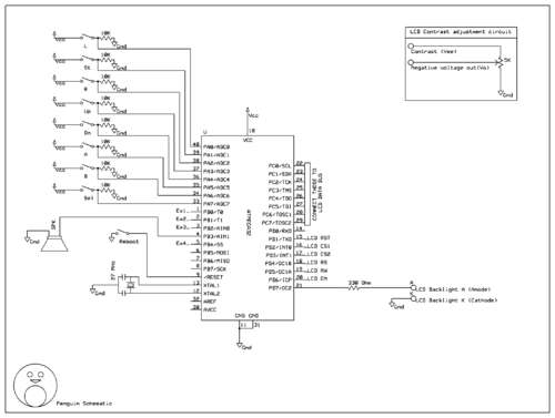
You might have troubles understanding it , so here are some explanations :
The rectangle you see in the top-right conrner explains how to connect the Vo and Vee (contrast pins) on the GLCD , with a 5K variable resistor , for contrast adjustment.
The EX text near some PORTB pins means that they can be used as an expansion port.Just plug them to pin headers.
The PORTC pins go in direct contact with DB0..DB7 on the GLCD
The PORTD1-PORTD6 have some text near them.That text shows with what pin on the GLCD to connect those pins.For example , the Enable pin on the GLCD will be connected to PORT D Pin number 6 , and so on.Reffer to your LCD’s datasheet for pinout.
PORTD7 is connected to a 330 Ohm resistor , and then into the A pin on the GLCD (LED backlight anode).The K pin on the GLCD (LED backlight cathode) is connected to Ground.
Demo
For more Detail: Build the Penguin game system using ATMega32/644 microcontroller
