Overview
After finishing Little More Serious Frequency Meter I had planned to make a suitable preamp and prescaler for it, and set about to gather ideas and parts. I was inspired by one fellow who had built the meter and the 2 line X16 character LCD display to show the output, succeeded in designing a preamp based on the BRF96 and modifying the circuit to get it to work at 99.999999 MHz. My intentions are to use the frequency meter between 100 and 200 MHz, so I found a prescaler, the Motorola, now On Semiconductor, MCT10280. For the preamp, I was able to buy some 2N3663 transistors. I would have like to have tried the BRF96, but could not find them stocked at any of my favorite distributors.
What was probably the most difficult part of the design was deciding what I really wanted the circuit to do and how to go about doing it, given the limitations of the available components. The resulting preamp can drive the counter from as little as 20 millivolts P-P input at a few KHz, but needs over 300 millivolts at 20 MHz, and can switch in a divide by 10 prescaler to extend the range to 300 MHz. I have used this at 338 Mhz to date. The data sheet limit for the 74HC4060 is 30 MHz, so performance over 300 MHz is expected by beyond specification.
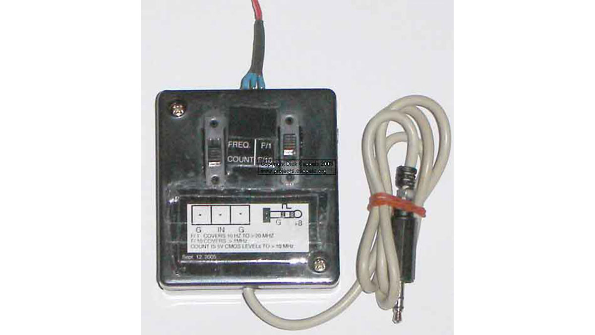
A Counter mode allows a direct coupled signal to drive the frequency meter in the counter mode.
The resulting preamp/prescaler design intended to operate within these frequency limitations:
MODE DESIGN SPECIFICATION
Count DC to several hundred kHZ (in practice, several MHz)
F/1 Frequency, no prescaler 10 Hz to 30 MHz
F/10 Frequency, 10X prescaler 10 MHz to 300 MHz (Mine worked at 338 MHz.)
These parameters are expected with an approximately 50% square wave up to frequencies of seveal MHz, and symmetric sine waves at higher frequencies. The primary limitation is based on the maximum clocking rate specification for the MM74HC6040 ripple counter in use in the Slightly More Serious Frequency Meter project. Selection of faster parts and careful circuit layout can extend the upper limit of the useful frequency range. The lower frequency imit is the lowest sine wave input frequency for the MCT12080 at which the input of the MCT10290 does not osccilate.
Signals applied to the input connector can be switched either through the AC path which includes the preamp and the prescaler, if switched into the circuit, or the DC path, which routes the signal to a Schmitt trigger buffer that then sends the signal on to the counter.
Regardless of how the signal is routed, it must first pass through an input protection network, which includes two schottky diodes and a zener clamp. The 1N5711 schottky diodes prevent the input signal from going more than a schottky diode drop below ground or above the power supply. I used Schottky diodes because they have a lower voltage drop than the PN protection diodes on the CMOS integrated circuit they are intended to protect, and as such, they will draw much more of the current from excessive input voltages than the input protection diodes in the integrated circuits.
The two 1N5226 zener diodes in series prevents the power supply from rising above 6.6 volts in case the input is accidentally connected to a low impedance source that is higher than 5 volts. The 47 Ohm resistor limits the input current in case of excessive voltage being applied to the inputs.
The input of the frequency meter requires a full 5 volt CMOS logic swing, and the prescaler’s output is less than 1 volt peak-to-peak, so the prescaler, when switched into the circuit, the signal goes through the prescaler, then the preamp, and the preamp drives the frequency meter through the Schmidt trigger buffers.
The MCT10280 prescaler can be set to divide by 80, 40, 20, or 10, as a function of which pins are tied to the power supply. I set this one to divide by 10 since it is adequate for my needs, and the mental calculation of multiplying the meter reading by 10 is not taxing. One problem with the MCT10280 is that if it doesn’t have an adequate input, the output is very noisy, which shows up as counts in the couple MHz range on the frequency meter. This noise shows up if the signal amplitude the signal frequency is too low. For this reason, I only intend to use the prescaler with inputs between 10 MHz and 300 MHz.
For more detail: Preamp and 330 + MHz Prescaler for A Little More Serious Frequency Meter using microcontroller

