Summary of Programming P89V51RD2 (8051 Microcontroller) on Breadboard
This tutorial details the step-by-step process of mounting a P89V51RD2 microcontroller on a breadboard, connecting essential peripheral components, and programming it to blink an LED with a one-second delay. It covers circuit assembly including power regulation, crystal oscillator setup, reset mechanisms, and LED interfacing, followed by guidance on software programming via an external video resource.
Parts used in the Programming P89V51RD2 Microcontroller Project:
- P89V51RD2 Microcontroller
- Switch
- 7805 Power Regulator
- 11.0592 Mhz Crystal Oscillator
- 33pf capacitor (x2)
- 10uf capacitor
- 100uf capacitor
- LED
- 270 Ohm Resistor
- Single Core wire
- Breadboard
- Wire stripper
- 9V battery
- Battery Snapper
- 10k resistor
In this instructable, I am going to give step wise procedure of programming a P89V51RD2 microcontroller on breadboard. If you are directly seeing this tutorial, then please see my previous tutorial on basic breadboard power stage here : https://www.instructables.com/id/Breadboard-5V-Pow…
In this tutorial we are going to mount the microcontroller on the breadboard and attach a single led to the microcontroller and program the microcontroller. The Led will blink with roughly 1 second of delay.
Step 1: Bill of Materials :
1. P89V51RD2 Microcontroller
2. switch
3. 7805 Power Regulator
4. 11.0592 Mhz Crystal Oscillator
5. 33pf capacitor – 2
6. 10uf capacitor – 3
7. 100uf capacitor
9. Led
10. 270 Ohm Resistor
11. Single Core wire
12. Breadboard
13. Wire stripper
14. 9V battery
15. Battery Snapper
Step 2: Description
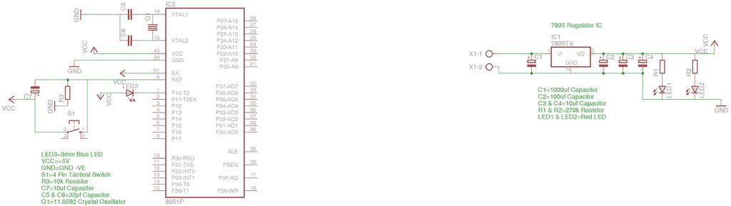
Now above is the circuit diagram which would be implemented in the this practical. As mentioned before, in earlier tutorial, that we are going to connect a single led to the microcontroller and program the microcontroller for it. The power stage will be same as the first chapter, so no need to touch the previous setup. Here, we are going to connect led to port1.0 which will blink with roughly 1 second of delay. We will recommend you to open the circuit diagram and practical tutorial pages in alternate tabs so you could just tally your breadboard circuit with the circuit diagram. Jump to the next step for beginning with the practical hands on. Happy hacking 🙂
Step 3: Breadboarding
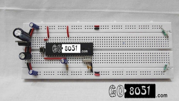
1. As you can see in the following Image, We have directly mounted the microcontroller on it. Also make sure that the notch (a small u shaped symbol) must point towards the 7805 regulator direction. Make sure you have left enough space in front and backward direction.This extra left space will be used for future where we will mount other things further.
2. Now, connect pin no 20 pin of microcontroller to the ground. Be careful with that don’t put it in VCC, else it might get damaged.
3. Now Connect the pin no 40 of microcontroller to VCC +5V as shown in the below image. The above gnd and this vcc will be power source for our microcontroller.
4. Now Connect pin no 31 (EA bar/VPP) to +5v. This is connected so because EA means external access. When it is given gnd, it will indicate that program has to be run from external memory. But in our case, we are going to run the program from internal memory. So we will make it high.
5. Now take the crystal oscillator (11.0592 Mhz) and place the legs of it between pin no 18 and 19 respectively. Don’t worry about how it is placed since it doesn’t have polarity. Just make sure you have placed it between specified pins only. Take a look at the picture for the reference.
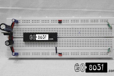
6. When placed it would look like this below picture. Make sure you leave extra space on the left of the crystal oscillator as we are going to mount capacitors there.
7. Now take a 33pf capacitor and place it between 19 pin of microcontroller and gnd respectively. Make sure that the pin is connected after the crystal oscillator, It would be a great placement if you could bend the legs at 90 degree to get a good placement and your breadboard will also look clean.
8. Now place the other 33 pf capacitor in the same way you placed the first one. But between the pins 18 and gnd respectively. This would complete the circuit for crystal oscillator which will provide clock cycles to the 8051 microcontroller.
9. After the placement, it would something look like the following picture. Try to place it cleanly.
11. Now take 10k resistor and put it between pin no 9 and gnd respectively. Pin no 9 is reset pin which will be used to reset the microcontroller.
12. Now take a 10uf capacitor and place the -ve terminal into pin no 9 and positive terminal into +5v power supply. See below image for reference.
13. It will look like this from above. Make sure the -ve point where the resistor is connected and +ve point where capacitor is connected are not short.
14. Now place the two pin tactical switch just above the microcontroller. This will be our reset switch.
15. Now connect the one end of tactical switch to vcc by joining it to pin no 40 of microcontroller 8051 as show in the following image.
16. Now connect the second pin of microcontroller to the pin no 9 of microcontroller. In this way the reset circuit will be completed. Recheck the connections and also tally it with the circuit diagram as it is important else your circuit will not work.
17. Now take a blue LED and bend their legs to 90 degree as shown in the below image. We are going to connect this led to our 8051 microcontroller.
18. Now place the negative end of LED to Port 1.0 or Pin no 1 of 8051 Microcontroller and the +v pin to the +ve line in the breadboard. Make sure you have connected anode to +ve and cathode to pin no 1.
(Note : We have not used resistor here, since the blue led is capable to handle voltage of over +5V if you are using other color, make sure you use a resistor of value 270 ohm else the led will get damaged. If you have difficulty differentiating between anode and cathode, the look at the led, the flat large surface is cathode and the the leg with thing surface is Anode)
Step 4: Programming the Microcontroller
This video will guide you, about how to program the 8051 microcontroller.
You can visit www.go8051.com for more tutorials on 8051 microcontroller.
Source: Programming P89V51RD2 (8051 Microcontroller) on Breadboard
- How do I connect the reset pin?
Connect a 10k resistor between pin 9 and ground, then place a 10uf capacitor with its negative terminal at pin 9 and positive terminal at +5v. - Can I run the program from external memory?
No, for this project you must connect pin 31 (EA bar/VPP) to +5v to ensure the program runs from internal memory. - What happens if I connect pin 20 to VCC?
Connecting pin 20 to VCC might damage the microcontroller; it must be connected to ground. - Do I need a resistor for a blue LED?
No, a blue LED is capable of handling over +5V without a resistor, but other colors require a 270 ohm resistor to prevent damage. - How do I identify the cathode and anode of an LED?
The flat large surface indicates the cathode, while the leg with the thin surface indicates the anode. - Where should the microcontroller notch be pointed?
The notch must point towards the 7805 regulator direction. - What frequency crystal oscillator is required?
An 11.0592 Mhz crystal oscillator is required for this circuit. - Which pin connects to Port 1.0 for the LED?
The negative end of the LED connects to Pin 1, which corresponds to Port 1.0.