Summary of Pulse Generator
Summary: The author built a precise pulse generator using an STM8S103F3 microcontroller with a 16 MHz crystal, leveraging timers (TIM1 as one-pulse and TIM2 for trigger frequency) and an ST7735 TFT display. A rotary encoder provides the UI to set frequency and pulse width, with firmware written in C (bare-metal) using STVD and Cosmic compilers. Constraints and design choices—timer prescalers, resolution limits, and shortest-pulse correction—are explained. Code is available on GitLab.
Parts used in the Pulse Generator:
- STM8S103F3 on development board
- 16 MHz crystal
- ST7735 1.8 inch TFT display
- 74HC14
- rotary encoder with button
- project box
- perfboard
- ST-Visual_Develop IDE (software)
- Cosmic Software STM8 compiler (software)
- ST-Link-V2 or clone (programmer)
- manuals about the STM8S103 (documentation)
- coffee
When you need pulses of any sort, long, short and with variable frequency you can use one or two 555 timers. That works, is easy to set up and is cheap. But it also limited to a certain range in frequency and pulse length.
If you want a precise pulse length you will need an oscilloscope to check it. The same goes for when you want an exact frequency.
I needed pulses of exactly 1us, 5us, 1ms and 5ms, I decided that trying to do that with 555 timers was not what I wanted.
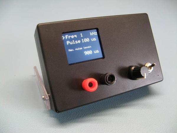
So I build a versatile pulse generator with a microcontroller and a crystal to produce exact results and a display to show the current values for frequency and pulse length.
EDIT: The code is now available on GitLab
https://gitlab.com/WilkoL/pulse_generator_st7735
Supplies:
STM8S103F3 on development board
16 MHz crystal
ST7735 1.8 inch TFT display
74HC14
rotary encoder (with button)
projectbox
perfboard
STMicroelectronics ST-Visual_Develop (IDE)
Cosmic Software STM8 compiler
ST-Link-V2 (or a clone)
manuals about the STM8S103
coffee
Step 1: The STM8S103F3
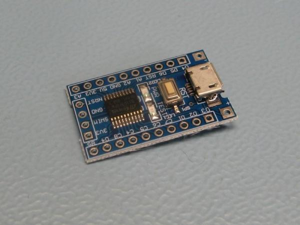
Usually I pick a STMicroelectronics STM32 or an Atmel (now Microchip) ATMEGA or even ATTINY microcontroller. This time I decided to use a STM8 microcontroller, the STM8S103F3. You can buy them on a breakout board for less than a euro.
While it is less capable than even the lowest of the STM32 series, it is somewhat comparable with the ATMEGA328 in speed and number of pins. But it only has a quarter of flash memory, just 8kByte.
The peripherals on the other hand are more capable than those in the ATMEGA328, esspecially the timers are awesome. And those are exactly what is needed for a pulse generator.
Step 2: IDE and Compiler
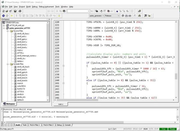
I program the STM8 in C with STMicroelectronics free “ST Visual Develop” (STVD) and the, also free, STM8 compilers from Cosmic-Software. (to download and use these programs you do need to register with their respective companies) Both programs feel rather old fashioned but they work well.
Most (all?) microcontrollers have pins with many alternate uses, they can be standard inputs or outputs, but can also be connected to one or more peripherals in the microcontroller. The selection of what alternate use a pin can have is dne with “Option Bytes” in a STM8S103F3. It can be done when the code is uploaded to the microcontroller but I prefer to use a separate program to do that called ST Visual Programmer, the option byte needed here is AFR0 (alternate function bye 0) see the screen print of the option bytes.
To upload the code into the microcontroller and to program the option bytes I have an official ST-Link-V2 but you can just as well use an incredibly cheap clone (3 euro).
Then there is STM8CubeMX. If you know the STM32 version of this program you will be disappointed with this program. The only real use of it is to make a layout of what pins get what function. You cannot produce any code with it as you can with STM32CubeMX.
Step 3: Standard Peripheral Library / Bare Metal
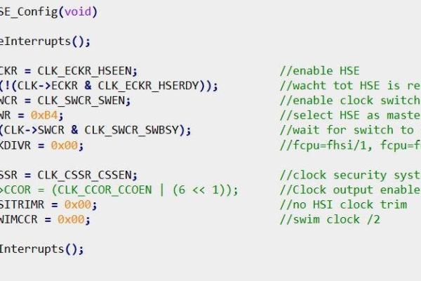
At first I used the Standard Peripheral Library (SPL) from STMicroelectronics, but I ended up coding on “the bare metal” as it is called. This means that instead of writing
GPIO_WriteHigh(GPIOC, GPIO_PIN_0);
you write
GPIOC->ODR |= GPIO_PIN_0; .
It does not make the code much smaller as the SPL is well written, but when the code was getting bigger, it didn’t fit in the available flash of the microcontroller when I used the SPL, but it did fit when written without the SPL. (in the finished program there are just a few bytes left)
The pictures show the configuration of the clock via the SPL and the Bare_Metal method. It takes a little time to get used to it, but it isn’t hard.
Step 4: Change of Mind
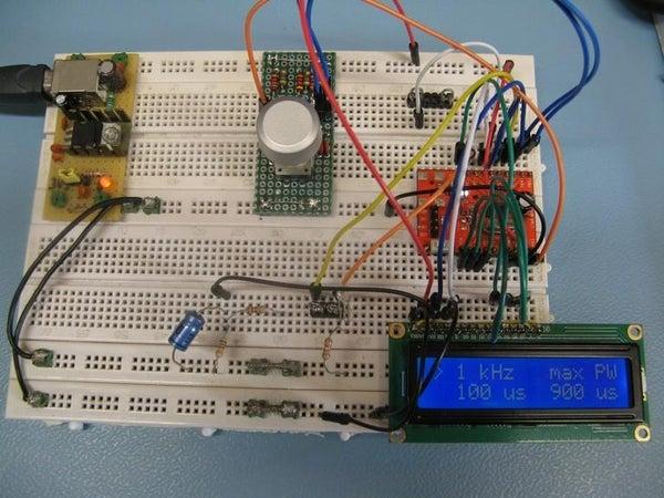
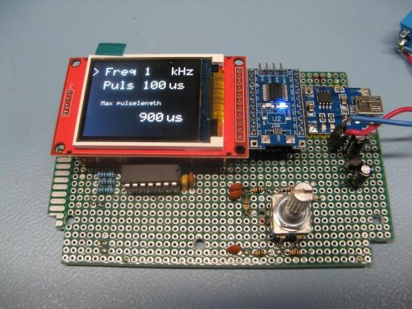
What also changed during development was the choice of display. I started with a LCD16x2 display but changed to a 1.8 inch ST7735 TFT. The main reason for this change was the size of the display, the LCD16x2 did fit in the project box I had in mind, but it would have used most of the frontpanel of it. The ST7735 is smaller so it made the layout of the frontpanel (if you can call it that) easier. As a bonus you can display a more text on it. Porting the drivers for the ST7735 from another project, with another type of microcontroller, proved to be easy.
Step 5: User Interface
A pulse generator doesn’t need a complicated user interface, in this case a single rotary encoder is enough. When the generator is switched on for the first time, the rotary encoder manages the frequency, press it once and the pulse width is changed.
There is a problem with being able to set the frequency and pulse width separately. Many combinations simply cannot work, you cannot produce pulses of 1 second length 50 times per second. I chose to make the maximum pulse length dependent on the frequency. (the other way round is also possible). This maximum possible pulse length is always shown. When you try to set a longer pulse length it ignores it. When you set a pulse length and increase the frequency it will do so until it reaches the maximum possible frequency at that pulse length and it changes the function of the rotary encoder from frequency to pulse length. There you can then decide to shorten it or leave it as it is, lengthening isn’t possible of course.
Step 6: Timers
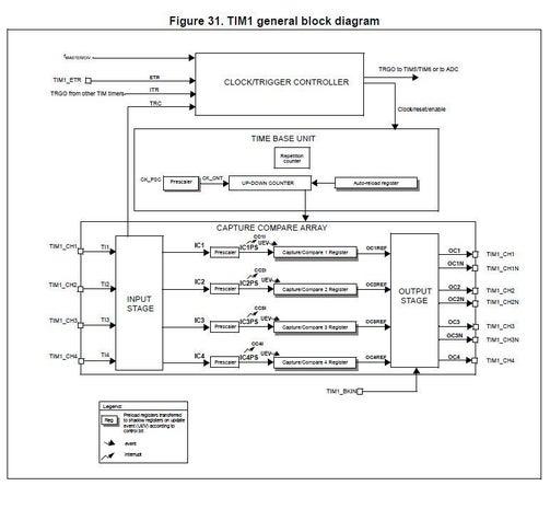
The STM8S103F3 has three timers, a basic timer, and general purpose timer and an advanced timer. The advanced timer (TIM1) can be used as a One-Pulse timer, just what is needed. When a One-Pulse timer is triggered it counts from zero to the value set in the Auto Reload Register (ARR) and then stops, until it receives another trigger.
TIM1 has four input/output channels of which one is an input used to trigger the timer and the second channel is the output for the pulse-output. Unfortunately it does not have the option to trigger it iternally from another timer, that option is reserved for bigger versions of this microcontroller, that have more timers. Not that it matters in this project, it would only have made one connection from one pin to the next pin unneccessary, but I like the idea of keeping as much as possible inside a microcontroller.
The general purpose timer (TIM2) is used to generate the frequency that triggers TIM1. While TIM1 has a prescaler that divides the clock frequency (16MHz) by any integer from 1 to 65536, TIM2 only has a prescaler that can be set to powers of two (1, 2, 4, 8, 16, 32 .. 32768). Only one output of TIM2 is used and is (as said) on the outside of the microcontroller connected to the input of TIM1.
Many frequencies can be generater with good accuracy or even exact values, but not all. One example: to create a frequency of 700 kHz from a clock of 16 MHz you need to divide it by 22.857, that simply isn’t possible with TIM2, you can divide by 23 to produce 695 kHz or divide by 22 which gives 727 kHz, I chose to produce 695 kHz as that is closest by. The next frequency, 800 kHz, can be produced exactly again. In the low frequencies ranges the error for “odd” frequencies, such as 30 Hz, is so small you can ignore it.
With the pulse length this problem is not there as both the prescaler and the Auto Reload Register of TIM1 can be set to any integer from 1 to 65536. But there is another problem with the shortest pulse lengths, the timer isn’t infinitely fast internally, it takes time to switch the output from 0 to 1 and back. This time is short, just 1 clock cycle, but that is 62.5ns and when the pulse you want is 300ns it is a big error. My solution is very simple, for the pulse lengths shorter than 1us the display shows the selected value plus 63ns. This way the display and the real pulse length are almost exactly equal.
Source: Pulse Generator
- What microcontroller was used for the pulse generator?
The project uses an STM8S103F3 microcontroller on a development board. - How are precise pulse lengths achieved?
Precise pulse lengths are produced using TIM1 as a One-Pulse timer driven by a 16 MHz crystal and configured in firmware. - Can the display show frequency and pulse width?
Yes, an ST7735 1.8 inch TFT display shows the current frequency and pulse length. - How is user input handled?
A single rotary encoder with a push button is used to adjust frequency and pulse width. - Does the project use 555 timers?
No, the project uses a microcontroller and crystal instead of 555 timers for better precision. - What development tools and compilers are used?
ST Visual Develop IDE and the Cosmic Software STM8 compiler are used for development. - How are frequency and pulse width limited relative to each other?
The maximum pulse length is made dependent on frequency; the UI prevents selecting impossible combinations and displays the maximum allowed pulse length. - How are very short pulses corrected for timer switching delay?
For pulses shorter than 1 microsecond the display shows the selected value plus 63 ns to account for the internal 1 clock cycle switching time. - Where is the project code available?
The code is available on GitLab at https://gitlab.com/WilkoL/pulse_generator_st7735.