Overview:
We decided to build transmitter and receiver modules for a radio-controlled (RC) car, as well as implement variable-speed motor control and a continuous steering function. The simple speed controls included in most RC kits seldom offer more than three forward speeds and one reverse speed; furthermore, steering controls in most “Radio Shack” toys only offer binary steering: Either the car is turning left, right or not at all. We felt that overcoming these limitations would make any RC car more realistic to handle and ultimately more fun to drive.

The Car
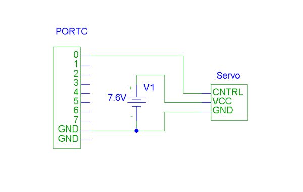
A Tamiya RC model kit was bought from a Maryland hobby store, along with a rudimentary radio control unit to verify that original unit’s operation. After making sure all parts were assembled correctly, the mechanical speed control, speed control servo, and radio receiver module were all removed. The car we selected already implements continuous steering with a servo attached to the steering linkage; however, because the radio receiver was no longer being used, we decided to leave the servo in and reverse engineer its interface.
The original implementation of speed control in the car consists of a servo which mechanically moves the arm of a simple high-power potentiometer. While the motion of the servo is continuous, the circuit only produces six discrete levels: three forward, two reverse, and neutral. Hobbyists in RC cars often replace this assembly with an electronic speed control (ESC), which uses pulse width modulation to provide a smooth speed control. We chose to simulate the function of these commercially available ESCs by using the microprocessor to modulate pulse width across the motor.
Communication
An RC car is of little value if the controls are tethered to the vehicle. However, we determined during the design process that the radio system was mostly irrelevant to the actual project, and that the time required to build the system would seriously impede on the rest of the project. We decided instead to use a pair of commercially available radio modems. The devices, made by National Semiconductor and used by Laplink under the “AirShare” label, claim to establish a 115 kbps serial connection at a distance of up to 30 feet with clear line-of-sight. While this range is inferior to that of commercially available radio control units, it is more than adequate to prove that the rest of the design works.
| Command | Opcode | Magnitude Range |
| Forward | 0000 | 0000 – 1111 |
| Reverse | 0001 | 0000 – 1111 |
| Left | 0010 | 0000 – 1111 |
| Right | 0011 | 0000 – 1111 |
| Start | 0100 | n.a. |
| Stop | 0101 | n.a. |
A simple communication protocol was established to send messages from the controller to the car. Because the connection is serial, we encode each command into a byte-long packet. The top nibble denotes the command, and the lower nibble represents the level at which the command is to be executed. For discrete operations (like headlights), the second nibble determines which functions are to be toggled. Communication travels one way from the controller to the car, which cuts down on the hardware required for either unit.
Controller
The original controller used spring centered potentiometers to produce analog signals which controlled the speed and direction of the car. The analog signals were transmitted to the car via a 75 MHz AM radio link.
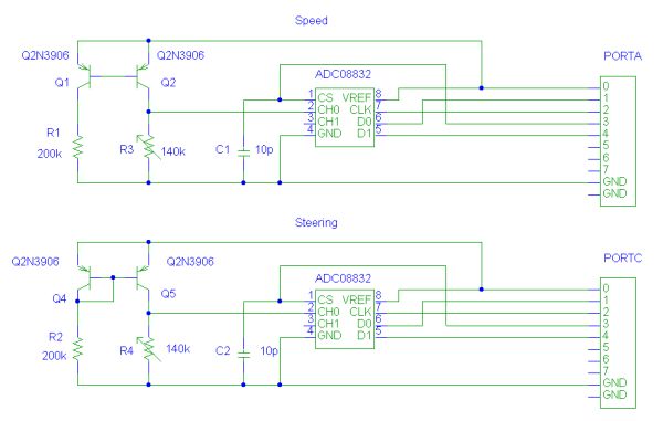
In order to emulate the true RC car experience, we decided that we needed something more visually intuitive than two potentiometers stuck into a breadboard. We purchased a simple PC joystick from Radio Shack and removed the “turbo” button circuitry. Using the existing interface cable, we were able to connect the internal potentiometers and pushbuttons to the receiver board without cosmetically altering the joystick.
Our design for the controller uses National Semiconductor serial ADCs to convert the analog waveform from the potentiometers to a digital signal. For example, the 8-bit value obtained from the forward/reverse potentiometer is compared against a known value for that potentiometer’s “centered” value; we can therefore determine whether the user intends to go forward or backward, and the rate at which she plans to do so. These data are used to generate the opcode and value to be sent to the car over the serial connection.
For more detail: EE 476 Final Project RC Car Controller

