Summary of Reversi Video Game Using ATmega32
This project implements the game Reversi on a TV using an Atmel ATmega32 microcontroller and Sega Genesis controllers. The system features single-player artificial intelligence, high-score tracking, and sound effects generated via a custom Digital-Analog Converter. The software handles menu navigation, game logic, and real-time graphics rendering while adhering to strict timing constraints for TV signal synchronization.
Parts used in the Reversi TV Game:
- Atmel ATmega163 MCU
- Atmel ATmega32 MCU
- STK-500 Development Board
- STK-200 Development Board
- Jensen Television
- Sega Genesis 3-button Controller
- DB-9 Female Connector
- Variou Wires
- Various Diodes
- Resistors
Introduction
“Our project implements the game, Reversi, on TV with a smart artificial intelligence and a host of other features!”
It’s our childhood game. We were so excited when we found out that we can actually build it for our 476 final project. We looked at the websites for various design of the game setup and the algorithm. Both my partner and I actually played for a few hours on the site before deciding on the project!
The design of our final project combines knowledge from previous labs on television display with C program that facilitates the Atmel ATmega32 microcontroller (MCU) to extract input signals from the controllers, provide artificial intelligence for the single-player mode, and to output the necessary graphics. We also built a Digital-Analog-Converter (DAC) using various diodes and resistors to interface the digital output from the MCU and the analog TV to create the sound effect. The running time of the code is particularly important in our final project as it is crucial to the synchronization of the TV signal. Two Sega Genesis controllers will be used to take in player inputs. The graphics of the game is outputted to the TV.
History
Wonder whats the history behind this simple but fun game? Here it is
Lewis Waterman patented the game Reversi in 1888, though he had been marketing games earlier than that date. James Mollett contested the claim that Reversi was Waterman’s game, as he noted that the rules and play were very similar to his own game invention, The Game of Annexation, originally published in 1870. Mollett’s Annexation game was played on a cross-shaped board, while Waterman’s Reversi was played on a normal chessboard.
It is Waterman’s version which is still played today, though it has not had a continuous history of popularity. During one of its down cycles, Japanese inventor Goro Hasegawa reinvented the game, with very minor differences, and marketed it in 1971 as Othello. Most players became familiar with that version of the game.
High Level Design
Rationale and Sources of Your Project Idea
In choosing our project, we wanted something that would require considerable ingenuity and complexity in the algorithm that would push the processing limits of the Atmel ATmega32 microcontroller (MCU) processor. After much brainstorming, a computer game that have some form of artificial intelligence, which would allow the user to challenge the computer, seems to be what we seek. Further pushing the limits of the microcontroller, we wanted to have excellent graphics to be displayed on the TV screen.
Background Math
The heart of our program is the artificial intelligence which plays against the user. Given the timing constraints of the TV, and the processing power of ATmega32, we cannot implement an algorithm that is overly complex. We had to find an algorithm that is sufficiently fast, yet smart at the same time. Our AI algorithm is a simple one-step-lookahead greedy algorithm which always places its piece on the square that would give it the most pieces. In the normal mode, it would also give preference to the corners and avoids the square immediately adjancent to the corner.
User Interface
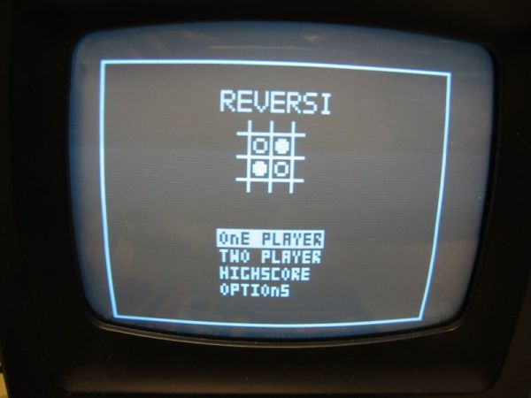
The game begins with a main selection screen allowing players to choose between one or two player modes. There are also menus which allows the user to view the highscores and set various options. The highscore function will keep track of the scores achieved by different players in the one player mode and rank them in the descending order.
After the user selects either 1- or 2-player modes, the game play screen will be set up. The initialize function will set up the gameboard and places four pieces in the initial position. . The screen displays player or computer’s turn by highlighting the player or computer. This feature is easy for the user to visualize. On the front panel, the score as well as the timing are displayed. The timer at the left hand corner of the screen keeps the timing in seconds. The player will also be prompted when he/she makes an illegal move. The user can return to the menu anytime by pressing button ‘B’. The computer will display a confirmation message before allowing the user to quit.
provided to the user during game play. On the front panel, the black or white square reminds the player or his/her own color. The rectangle box indicates who’s turn it is. There’s also instant score and time display. In this scene, the player just attempted a illegal move and we can see that the warning is still shown.
At the end of the game, a winning tone will be played if no songs are selected. The scoring is based on the number of pieces each player obtains in the end. The number will be displayed on the screen and the winner is shown.
Logical Structure
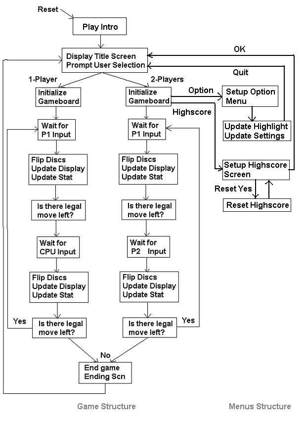
The main C program is basically divided into 3 components that are controlled by a large FSM:
i) Menus Structure
ii) Game Logic
iii) Miscellaneous Features
The Menus Structure component consists of mostly graphical commands that setups and animates the various menus (Main, Options, Highscore) and provides the necessary input polling.
The Game Logic component consists of the artificial intelligence algorithm used in the single player mode and support for the dual player mode. This is the most complex part of our code and includes many supporting functions for the AI and functions to continuously update the game board and peripheral graphics.
We have an array of various bell and whistle features in our game. Aside from the two core components, theres also significant coding to play the songs and sound effects, scorekeeping, and time tracking. The coding for the song is programmed onto a separate Atmel ATmega163 chip which resides on a sister STK-200 board. The STK-200 board is linked to the main STK-500 board through an I/O port, and a square pulse activates the various hardprogrammed songs on the sister MCU. The main program flow is listed below:
Hardware / Software Tradeoff
Our project is mainly software driven. The hardware was used mainly as I/O devices solely. Digital-Analog Converters (DACs) were built to facilitate the conversion between the digital output and the analog signals required by the TVs audio and video input.
As our project is mainly software driven, the demand on the MCU was great. The tight raster required by the TV signal in combination with the complexity of the graphics and the O(n4) function calls of the AI demanded a fast MCU. The ATmega163 MCU we used originally were unable to handle these tasks. By upgrading to the ATmega32, we were able to allow up to 128×100 in the resolution. However, even with ATmega32, we had to break many graphics and AI processes down to perform over multiple cycles. Memory was also getting tight due to the long length of the code (~3300 lines). We moved our ATmega163 MCU to the STK-200 board to control the sound component and it worked perfectly.
Parts list:
|
Item |
Quantity |
Costs |
| Atmel ATmega163 and ATmega32 MCU |
1 |
$� 0.00 |
| STK-500 Development Board |
1 |
0.00 |
| STK-200 Development Board |
1 |
0.00 |
| Jensen Television |
1 |
0.00 |
| Sega Genesis 3-button Controller (eBay) |
2 |
13.00 |
| DB-9 Female Connector (Radio Shack) |
2 |
2.98 |
| Various Wires, etc. |
|
0.00 |
| TOTAL |
$15.98 |
For more detail: Reversi Video Game
- What algorithm does the AI use?
The AI uses a simple one-step-lookahead greedy algorithm that places pieces to maximize its count. - How are player inputs captured?
Two Sega Genesis controllers are used to take in player inputs via DB-9 connectors. - Does the system support two players?
Yes, the main selection screen allows users to choose between one or two player modes. - How is sound produced?
A Digital-Analog Converter built with diodes and resistors interfaces the MCU output to the TV audio. - Can users view their high scores?
Yes, menus allow users to view highscores which track and rank scores in descending order. - How does the user return to the menu?
The user can return to the menu anytime by pressing button B. - Why was the ATmega32 chosen over the ATmega163?
The ATmega32 was required because the ATmega163 could not handle the tight raster and processing demands. - What happens if a player makes an illegal move?
The user will be prompted with a warning message when attempting an illegal move.