Introduction
Robo-SLR provides a remotely controllable stand for a Canon EOS 550D DSLR camera, allowing for adjustable tilt and pan functionality along with the ability to remotely view through the camera’s viewfinder and take photos.
An ATmega1284 microcontroller is used to control camera functions as well as tilt and pan over a wireless bluetooth connection to a PC. This allows a photographer to easily photograph himself or herself by setting up the camera once, and then make adjustments in tilt and pan as necessary based on feedback from the camera. Using a PC to make these adjustments is much more convenient, and much more accurate because the photographer can immediately see what the photo is going to look like.

High Level Design
Robo-SLR was inspired by our recognition of the massive unrealized potential for cheap camera control systems. The ability to remotely manipulate the physical positioning of a camera coupled with the ability to remotely take photos and manipulate camera parameters yields many benefits we’re aiming to unlock. Photographers will be able to experience a new degree of freedom without being as tightly bound to their cameras.
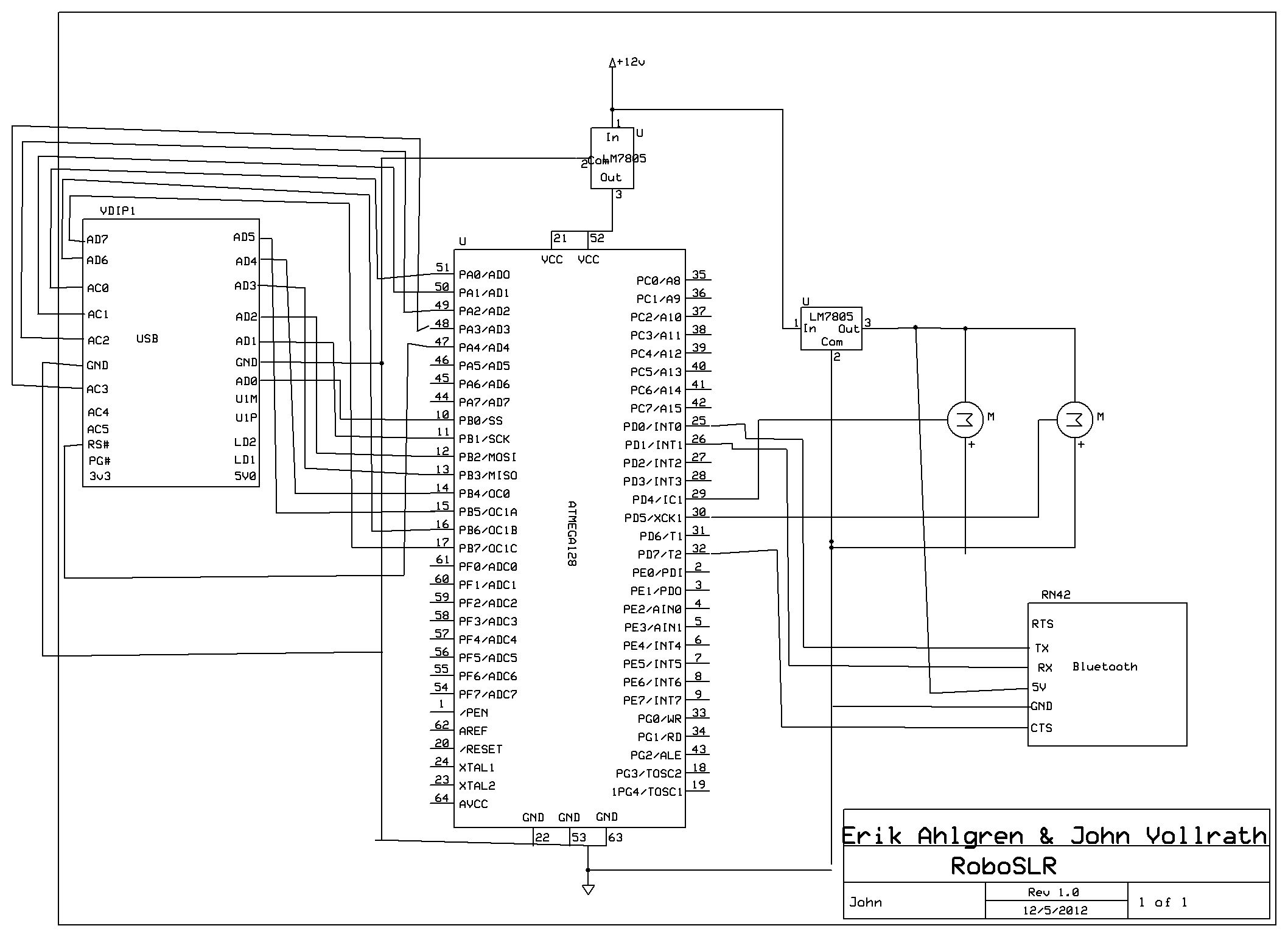
The idea behind Robo-SLR is to give freedom to the photographer to step away from their camera without sacrificing too much freedom to operate their camera. Therefore, the flow of our system is naturally user-driven. The flow starts when a user requests something of Robo-SLR. This request may be a PTP command to the camera, or a request to adjust the position of the camera with the servos. Either way, the command is sent through bluetooth on the user’s PC to the BlueSMiRF module. The BlueSMiRF module then transmits the received data to the ATmega1284 via UART. Upon receiving a command, the ATmega decides whether it is a servo command or a PTP command. If it’s a servo command, the ATmega adjusts the pulsewidth of the appropriate servo accordingly. Otherwise, the microcontroller figures out which PTP command to send, and sends it over a parallel connection to the FTDI USB host. The FTDI USB host then relays the PTP request to the camera, and returns the response and any data to the microcontroller. The microcontroller then relays the response and/or any data to the PC through the BlueSMiRF module if necessary.
System Diagram
Everything we have done and more has already been achieved by commonly available PC software such as gphoto2. However, PC software does not allow as much freedom or flexibility as a microcontroller does out in the field. Therefore, we have
Standards
Robo-SLR uses the IEEE 802.15.1 standard for bluetooth communication.
The PTP protocol is used for communicating with the camera.
Software Design
Bluetooth
Our project used the BlueSMiRF Silver module to connect a user’s PC to the ATmega1284 microcontroller. The UART feature of the microcontroller was used to handle sends and receives through the BlueSMiRF, and we were able to achieve up to 500kb/s baud rate. In order to provide hardware flow control, we used interrupts on the input buffer for the clear-to-send signal. When the input buffer is empty, clear-to-send is set low (it is active low). When the input buffer is full, clear-to-send is set high. Both of these occur through the use of interrupts. Also, we found the previous UART code to be a bit high in overhead, so instead we opted to create our own getchar and putchar functions.
Servo Control
We controlled two servos with timer1 on the ATmega1284 microcontroller through the use of pulsewidth modulation. The servos accept a 50Hz pulse, and center for each servo is 1.5ms, which corresponds to a counter value of 375 with a prescaler of 64. The range of both servos is 0.9ms to 2.1ms which corresponds to counter vlaues of 225 and 525 respectively. Every adjustment request only modifies the output compare register by 1, because the camera is heavy and it is desireable to make slow, steady adjustments.
Camera Control
Before the advent of the Picture Transfer Protocol (PTP), manufacturers implemented proprietary protocols to remotely control cameras. Since high-performance, cheap microprocessors have become popular, the demand for automated control has drastically increased. In order to make implementations more economical and scalable, the PTP was created.
The PTP defines a handful of constructs that the entire protocol relies upon. Foremost, a session is a logical connection between the Initiator and the Responder. Through this session, transactions are passed back and forth. A transaction can be one of four types: (1) a command packet, (2) a data packet, (3) a response packet, and (4) an event packet. The sequence of communication works like this: one of the devices issues an operation request to the other; depending on the operation code, the responder responds with a corresponding response packet. If the response requires more data than can fit in the response packet (more than 12 bytes), then a data packet is generated and sent before the response packet. The requester is responsible for knowing how to handle the response and data packets depending on what command it sent.
The command, data, and response phases are all synchronous – the PTP protocol does not allow simultaneous transactions. However, the Event packet is handled asynchronously from when it occurred. An example of when an Event type is used is when a Requester commands that a device take a photo; in order to know when the photo has been taken and stored, the responder will queue an Event when the photo is captured. The Requester then polls for the Event, and the responder is issued. One can see this is an intricate combination of synchronous processing within an asynchronous environment.
Perhaps the most challenging part of this project is knowing how to form the command, data, and response packets for the specific task you want to achieve. While the PTP defines a standard set of commands, responses, and properties that each manufacturer is responsible for implementing, the PTP can not possibly embody every feature that one manufacturer might want. As such, manufacturers create their own operations, data packets, and responses, which can do exciting things like take Live View Previews (the sought-after feature of our project). The problem with this solution is that there is almost no documentation available.
Without documentation to tell us how to construct the packets, we were forced to reverse engineer Canon’s messages. Using a combination of tools, we issued commands to the camera and used USBlyzer to sniff the USB packets being sent back and forth. Through this, we successfully discovered the command codes needed to gather a Live View Preview from the Canon EOS 550D. However! There is more than just the opcode in a PTP packet – there are also attached parameters that are crucial to issuing the right command, and responding appropriately to data and response packets.
In this example, a program is trying to tell the Canon EOS 550D to gather a Live View Preview with the command packet (18 00 00 00 01 00 53 91…). However, the camera continuously responds with (0C 00 00 00 30 00 02 A1…), which means it’s busy and not able to complete the request. When we originally ran the command packet on our microcontroller, we were confused because we knew we were using the correct command packet. As it turns out, the program must continuously request a Live View Preview, and eventually the camera will respond with a “Yes, here is your image!” type of message.
The final challenge to hurdle dealt with handling a large data packet on the AVR. Our plan was to read one byte from the FTDI controller, and then issue that byte to the Bluetooth radio. After the byte was out of the UART buffer, another byte could be read from the FTDI chip. This philosophy would have worked well, however, the control logic for determining when a data packet actually comes it tricky. There are false data packets, such as the one in the photo, where the camera returns a data packet, but it’s merely a data packet saying “Hey, I’m not ready!” With the combination of a jubilee of other bugs, the Live View Preview feature was not able to be implemented. Our attempt at doing so can be found in PTP_basic.h:PTP_CANON_GetLiveView().
Parts List:
|
Part
|
Qty
|
Cost
|
Notes
|
|
BlueSMiRF Silver
|
1
|
$39.95
|
Bluetooth Module. Purchased from Sparkfun
|
|
755HB
|
1
|
$27.99
|
Hitec Servo Motor. Purchased from Amazon
|
|
HS81
|
1
|
$13.67
|
Hitec Servo Motor. Purchased from Amazon
|
|
FTDI VDIP1
|
1
|
$5.00
|
USB host module. Borrowed from the lab
|
|
ATmega1284
|
1
|
$5.00
|
ATmega1284 and board from the lab
|
|
Assorted Washers
|
20
|
$0.50
|
16 small washers and 2 larger washers. Purchased from Lowe’s (part numbers 409485, 63306)
|
|
6-32 hex nuts
|
8
|
$0.50
|
Nuts for the servo arm bolts. Purchased from Lowe’s (part number 409466)
|
|
6-32 x 3/8 bolts
|
8
|
$0.50
|
Bolts for the servo arm mounts. Purchased from Lowe’s (part number 409487)
|
|
1/4 hex lock nut
|
1
|
$0.10
|
Nut for camera mount bolt. Purchased from Lowe’s (part number 63403)
|
|
1/4 x 3/4 hex bolt
|
1
|
$0.10
|
Bolt for the camera mount. Purchased from Lowe’s (part number 55817)
|
|
Canon EOS 550D
|
1
|
N/A
|
John’s camera. Owned for more than a year.
|
|
Bread board
|
1
|
N/A
|
John’s breadboard. Owned for more than a year (previous projects)
|
|
12V Power Supply
|
1
|
N/A
|
John’s old power supply from external hard drive. Owned for more than a year
|
|
Laptop
|
1
|
N/A
|
Erik’s laptop. Owned for more than a year
|
|
Voltage Regulator
|
1
|
N/A
|
5v regulator. John has owned it for more than a year (old FSAE supply).
|
|
Scrap Sheet Metal
|
N/A
|
One 6″ x 3″ piece and one 3″ x 2″ piece. Scavenged from the ELL
|
For more detail: RoboSLR Using Atmega644