Summary of Setting up Atmel Studio for USBasp and AVR Programming
This blog explains configuring Atmel Studio on Windows to compile AVR code with WinAVR and upload using USBasp. It covers installing software, creating a WinAVR toolchain flavor, adding an External Tool that runs avrdude with proper arguments, compiling a project, connecting the USBasp to an ATmega (example ATmega8), using an external crystal, uploading the HEX, and basic troubleshooting steps for communication failures.
Parts used in the Setting up Atmel Studio for USBasp and AVR Programming:
- Windows 10 PC
- Atmel Studio 7
- WinAVR
- USBasp programmer
- USBasp based AVR development board (with ZIF socket and GPIO pins)
- AVR microcontroller (example ATmega8)
- External crystal (optional)
- Two 22pF ceramic capacitors (for external crystal)
- USB cable (to connect USBasp to PC)
It can be a lot confusing someone for who just started programming in AVR environment. Atmel studio is the best IDP [Integrated Development Platform] for AVR programming and embedded system development. It takes awful lot of time just to get installed. But once you’re done configuring the IDP for AVR programming, there’s no way you’re going back!

In case you don’t know you can only install Atmel Studio in Windows. So if you’re using linux, this blog post won’t be of any help for you.
First of all, let’s take a look at my current system configuration
Software
- Windows 10
- Atmel Studio 7 (Version: 7.0.1188)
- WinAVR
Hardware
- USBasp
Or,
- USBasp based AVR Development board
USBasp
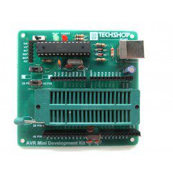
In case you don’t know what a USBasp looks like, here’s an image for you.
AVR Development Board
I’m using a USBasp based development board. It supports USBasp driver, so even if I am configuring my IDP using this development board. It should work on your USBasp too.
This development board has a ZIF socket where you can put AVR chips and program using the board. No extra connections are necessary. There are pinout slots for GPIO.
Make sure you have Atmel Studio, WinAVR and a USBasp to follow this tutorial.
First Step
Install both Atmel Studio and WinAVR. You can follow the guided instruction embedded in the installation wizard.
Next step
Configuring Toolchain for Compilation
Since I am going to upload my codes to AVR using avrdude. I need to compile the codes first using the same toolchain.
To do that, I need to make a custom toolchain configuration.
Step 1
Go to Tools > Options > Toolchain
Select Atmel AVR 8-bit (Cpp Language) option from the dropdown menu.
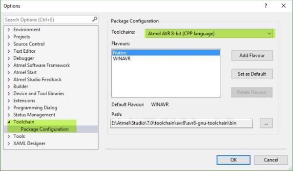
Step 2
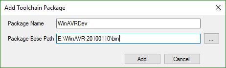
Click Add Flavour, then set the package name “WinAVRDev” or anything you may like.
For the package base path go to WinAVR installation directory and find the bin folder. Now copy the path and paste it. [For me it was E:\WinAVR-20100110\bin ]
You can make the newly created toolchain package default by clicking on to the Set as Default button.
If you’re done with the toolchain package configuration, click OK to close the Dialog Window.
Creating External Tool for USBasp
To upload the compiled hex files. You need to configure the external tool for USBasp. If you don’t create an external tool for USBasp that’s fine too, then you need to type the avrdude commands to upload or use other software to upload the hex file for you.
Why bother when Atmel Studio can help you on both code compilation and hex file uploading process?
Step 1
Go to Tools > External Tools
Click add and fill up the blanks with following strings.
Check: Use Output window
Uncheck: Prompt for arguments, Treat output as Unicode
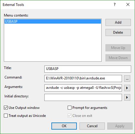
Title: You can give any title you want.
Command: This will initiate the avrdude program, so you need to put the avrdude directory path in this blank. For me it was E:\WinAVR-20100110\bin\avrdude.exe
Arguments: This is the most tricky part. This is the arguments section where you need to pass specific arguments to do specific tasks. Since I am using the external tool as the program code loader. I need to put the command which I’d use in avrdude for uploading codes.
You can find a lot about avrdude commands here.
Here is the argument that I provided
avrdude -c usbasp -p atmega8 -U flash:w:$(ProjectDir)Debug\$(TargetName).hex:i
You can see that I put atmega8 here. That’s because I am programming my ATmega8 chip.
If you need to program other microcontroller. You must change the chip name.
Testing the configuration
Creating new project and device selection
Now we need to test if my configuration is working properly. Create a new project [GCC C++ Executable Project].
Project compilation
Build > Build Solution
If you can relate the last line of your output with mine then you’ve successfully compiled your program and you can upload it right away!
=== Build: 1 succeeded or up-to-date, 0 failed, 0 skipped ==
Uploading the *.HEX File
By uploading the hex file I mean programming the avr chip. Remember, up to now you’ve only compiled the project and you haven’t uploaded the code to your atmega chip yet.
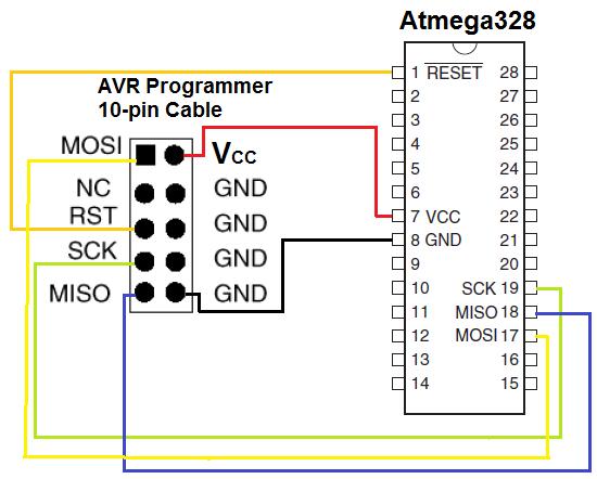
Make proper connections with the USBasp and your AVR microcontroller.
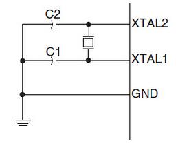
Using external clock
If you use external crystal then the you’ll be needing two 22pF ceramic capacitors too, connect the components according to the following diagram
Now connect the ATmega chip to the USBasp
Finally uploading the Code
Before jumping into that, don’t forget to connect the USBasp to your PC first!
I am now going to use the External Tool to upload the hex file to the avr chip.
A successful upload looks like this.
Troubleshooting
If any error occurs, first of all, check your WinAVR directory.
For the following error take the mentioned steps.
avrdude.exe: error: programm enable: target doesn't answer. 1avrdude.exe: initialization failed, rc=-1Double check connections and try again, or use -F to overridethis check.avrdude.exe done. Thank you.
It means your USBasp can’t communicate with the target chip [The chip you’re going to program].
Steps:
You can take the following steps to resolve the problem
- Double check if it’s powered properly with +5V DC.
- Short AVCC and VCC together and both GNDs together.
- Check the crystal’s and the ceramic capacitors’ connection
If the steps don’t work, your chip may be bricked. Try the whole process on a new working chip.
Source: Setting up Atmel Studio for USBasp and AVR Programming
- Can I install Atmel Studio on Linux?
No, the article states Atmel Studio can only be installed on Windows. - What toolchain flavor should I add for WinAVR?
Add a custom flavor based on Atmel AVR 8-bit (Cpp Language) and point the package base path to the WinAVR bin folder, e.g., E:WinAVR-20100110bin. - How do I configure Atmel Studio to upload with USBasp?
Create an External Tool pointing to avrdude.exe and use avrdude arguments such as avrdude -c usbasp -p atmega8 -U flash:w:$(ProjectDir)Debug$(TargetName).hex:i. - Do I need to change anything if I use a different AVR chip?
Yes, change the device name in the avrdude arguments to match your microcontroller (the article uses atmega8 as an example). - How do I know compilation succeeded in Atmel Studio?
The output should show Build: 1 succeeded or up-to-date, 0 failed, 0 skipped. - What must I connect when using an external crystal?
Use the external crystal and two 22pF ceramic capacitors connected as shown in the article diagram. - What does avrdude error programm enable: target doesn't answer mean?
It means the USBasp cannot communicate with the target chip. - What steps fix target doesn't answer communication errors?
Check the target is powered with +5V DC, short AVCC and VCC and both GNDs together, and verify the crystal and capacitor connections; if unresolved try a different chip.