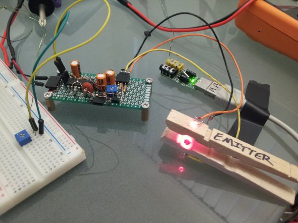
Of the hundreds of projects I’ve shared over the years, none has attracted more attention than my DIY ECG machine on the cheap posted almost 4 years ago. This weekend I re-visited the project and made something I’m excited to share! The original project was immensely popular, my first featured article on Hack-A-Day, and today “ECG” still represents the second most searched term by people who land on my site. My gmail account also has had 194 incoming emails from people asking details about the project. A lot of it was by frustrated students trying to recreate the project running into trouble because it was somewhat poorly documented. Clearly, it’s a project that a wide range of people are interested in, and I’m happy to revisit it bringing new knowledge and insight to the project. I will do my best to document it thoroughly so anyone can recreate it!
The goal of this project is to collect heartbeat information on a computer with minimal cost and minimal complexity. I accomplished this with fewer than a dozen components (all of which can be purchased at RadioShack). It serves both as a light-based heartbeat monitor (similar to a pulse oximeter, though it’s not designed to quantitatively measure blood oxygen saturation), and an electrocardiogram (ECG) to visualize electrical activity generated by heart while it contracts. Let’s jump right to the good part – this is what comes out of the machine:
That’s my actual heartbeat. Cool, right? Before I go into how the circuit works, let’s touch on how we measure heartbeat with ECG vs. light (like a pulse oximeter). To form a heartbeat, the pacemaker region of the heart (called the SA node, which is near the upper right of the heart) begins to fire and the atria (the two top chambers of the heart) contract. The SA node generates a little electrical shock which stimulated a synchronized contraction. This is exactly what defibrillators do when a heart has stopped beating. When a heart attack is occurring and a patient is undergoing ventricular fibrillation, it means that heart muscle cells are contracting randomly and not in unison, so the heart quivers instead of pumping as an organ. Defibrillators synchronize the heart beat with a sudden rush of current over the heart to reset all of the cells to begin firing at the same time (thanks Ron for requesting a more technical description). If a current is run over the muscle, the cells (cardiomyocytes) all contract at the same time, and blood moves. The AV node (closer to the center of the heart) in combination with a slow conducting pathway (called the bundle of His) control contraction of the ventricles (the really large chambers at the bottom of the heart), which produce the really large spikes we see on an ECG. To measure ECG, optimally we’d place electrodes on the surface of the heart. Since that would be painful, we do the best we can by measuring voltage changes (often in the mV range) on the surface of the skin. If we amplify it enough, we can visualize it. Depending on where the pads are placed, we can see different regions of the heart contract by their unique electrophysiological signature. ECG requires sticky pads on your chest and is extremely sensitive to small fluctuations in voltage. Alternatively, a pulse oximeter measures blood oxygenation and can monitor heartbeat by clipping onto a finger tip. It does this by shining light through your finger and measuring how much light is absorbed. This goes up and down as blood is pumped through your finger. If you look at the relationship between absorbency in the red vs. infrared wavelengths, you can infer the oxygenation state of the blood. I’m not doing that today because I’m mostly interested in detecting heart beats.
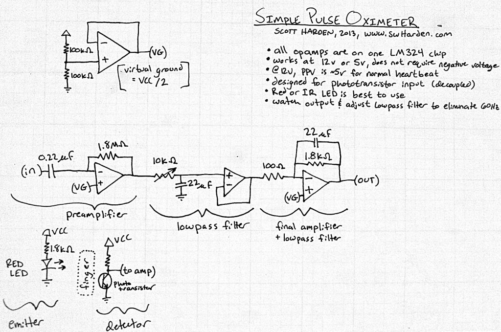
For operation as a pulse oximeter-type optical heartbeat detector (a photoplethysmograph which produces a photoplethysmogram), I use a bright red LED to shine light through my finger and be detected by a phototransistor (bottom left of the diagram). I talk about how this works in more detail in a previous post. Basically the phototransistor acts like a variable resistor which conducts different amounts of current depending on how much light it sees. This changes the voltage above it in a way that changes with heartbeats. If this small signal is used as the input, this device acts like a pulse oximeter.
For more detail: Simple DIY ECG + Pulse Oximeter (version 2)


