Summary of SIMPLE SOFT LATCH SWITCH USING PUSH-BUTTON
This article proposes a cost-effective "soft latching switch" circuit as an alternative to expensive mechanical toggle switches for large-scale production. By replacing the mechanical component with push-button logic using transistors, the design meets requirements for low cost, minimal parts, and zero current draw when off. The solution utilizes a simple two-transistor configuration inspired by David Jones to achieve reliable ON/OFF operations without dedicated modules.
Parts used in the Soft Latching Switch:
- Push-button
- Two transistors (PNP or NPN)
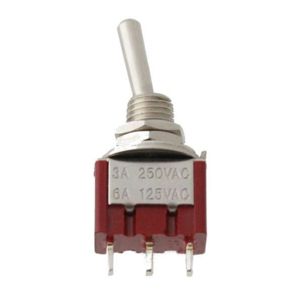
Latching Toggle switches are one of the most popular kinds of switches, from their use by kids in basic electricity classes to their use in prototypes and more advanced products, they provide a familiar and reliable way to close or open a circuit. This makes them the go to switch for designers in most applications but while they may be perfect for switching your device on/off in a low volume project, their price does not make them worthy for use in large scale projects as they can be expensive (usually over a dollar depending on the current rating you require), comparing the fact that you could buy a microcontroller and other components for that price. Due to these costs, designers, have been replacing (where possible) the toggle switch with the momentary push buttons which are way more cheaper especially when you are trying to get the cost down on your product.
For today’s project, I thought it will be a good idea to look at the latching toggle switch to see if we can create a cheaper alternative which can be used for ON/OFF switch operations in devices in large scale production. One of the major factors behind the cost of the latching toggle switch is that they are mechanical in nature, thus for our solution, we will ensure we don’t turn the same part by creating a soft latching switch circuitry but we will use a push-button instead.
DESIGN REQUIREMENTS
As with any design, we will start out by outlining the requirements for our Soft Latching Switch. All of the requirements are geared towards ensuring the cost is kept low and performance is either greater or of the same quality with the mechanical latching toggle switch. The requirements are:
- Standalone; The circuitry should be independent of the system in which it is to be deployed.
- Minimal Parts; It should use very little components to keep the size small and cost as low as possible.
- Basic Parts Only; We won’t be using any special/dedicated modules
- No current drawn when Off
- Cheaper than the mechanical latching toggle switch.
DESIGNING THE SWITCH
For today’s design, we will draw inspiration from a design by David Jones. The switch circuitry (shown in the schematics below) is made up of two transistors which could either be PNP or NPN. The transistors work hand in hand such that the flow of base current to turn “ON” one of the transistors turns ON the other transistor. To explain better, consider the schematics below.
Read more: SIMPLE SOFT LATCH SWITCH USING PUSH-BUTTON
- Why are designers replacing toggle switches?
Designers replace them because mechanical toggle switches are expensive, often costing over a dollar, while microcontrollers and other components can be bought for that price. - What is the main factor behind the high cost of latching toggle switches?
The major factor is that they are mechanical in nature. - How does the soft latching switch reduce costs?
It avoids turning the same part mechanically by using a push-button instead and ensures no special or dedicated modules are used. - What are the core design requirements for this circuit?
Requirements include being standalone, using minimal basic parts, drawing no current when off, and being cheaper than mechanical toggle switches. - What components make up the switch circuitry?
The circuitry is made up of two transistors which could either be PNP or NPN. - How do the two transistors work together?
The flow of base current to turn one transistor on turns on the other transistor. - Who inspired the design of this switch circuitry?
The design draws inspiration from a design by David Jones. - Is this circuit independent of the system it is deployed in?
Yes, the requirement states the circuitry should be independent of the system.