Summary of Smart Fire Detection: A Wireless Sensor Network Approach for Indoor Arenas
This article details a wireless fire alarm system using ATMEGA32 microcontrollers with Master and Slave units communicating via ZigBee. The system integrates heat and smoke detectors, transmitting data wirelessly to a central controller for analysis and alarm activation. It aims to reduce costs and power dissipation compared to existing systems while offering intelligent detection capabilities for large areas.
Parts used in the Wireless Fire Alarm System:
- ATMEGA32 Microcontroller
- ZigBee Modules (XBEE)
- Heat Detectors
- Smoke Detectors
- LCD Display
- Siren
- Relays
- Flasher
Abstract
This document details the development and implementation of a wireless fire alarm system, managed by an ATMEGA32 microcontroller, featuring Master and Slave Unit Controllers. The system receives input signals from normally opened warning devices like heat detectors and/or smoke detectors, with the unit containing these detectors referred to as the slave unit controller. The output signal is transmitted to the Master Unit Controller for analysis. The communication between MASTER and SLAVE units utilizes a wireless transmission line employing ZIGBEE modules. Upon comparing our design with existing marketing systems (1) and (2), it is evident that our design exhibits the lowest total power dissipation.
1. Introduction
In the foreseeable future, we anticipate that buildings will be outfitted with an array of wireless sensors and actuators, seamlessly integrated into an overarching building management system. Among these sensors are devices designed to monitor fire and smoke, promptly responding to detected events by facilitating the identification, localization, and tracking of fires [1]. This approach not only enhances fire response capabilities but also contributes to the reduction of system components and maintenance requirements. Our ongoing efforts involve the development of diverse techniques and application solutions aimed at realizing this vision of improved fire response through wireless embedded systems [1].
The automatic fire alarm system, a critical component in this context, offers real-time surveillance, monitoring, and automated alarm functions. It issues early warnings upon the occurrence of a fire, thereby mitigating potential damage. Wireless sensor networks have emerged as a pivotal technology in environmental monitoring, as well as home and factory automation in recent years. We have specifically designed an automatic fire alarm system based on wireless sensor networks for high-rise buildings. To enable early fire disaster extinguishing, a multitude of detectors measuring smoke concentration or temperature at regular intervals are strategically deployed within buildings [2].
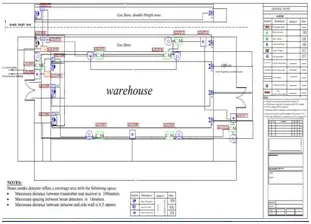
Given the vital role of fire alarm systems in ensuring life safety, they demand meticulous design and installation for optimal reliability. The control panel serves as a central hub, receiving information from input devices [3], processing it, and triggering alarms through sirens and/or strobes. Three fundamental types of fire alarm control panels exist: conventional panels, addressable panels, and wireless panels. Our presented design represents a modification of the conventional fire alarm system, transforming it into an intelligent and wireless system that retains the advantages of traditional alarm systems while incorporating cutting-edge wireless technology. This design is tailored for expansive areas such as hangars, stores, and shops, aiming to minimize the overall costs associated with system components and maintenance in these spaces.
For ongoing system maintenance, all necessary components, including detectors, controllers (ATMEGA32) [1], wireless modules (XBEE), and LCDs, are readily available in the market. This paper provides an overview of our work in five key areas: an explanation of the design structure, a flow diagram, a discussion of the Zigbee module, Wireless Sensor Networks (WSNs), and the outcomes of the system.
2. Fire detection and alarm system
The Fire Detection and Alarm System refers to electronic equipment designed to detect fires and sound alarms as a warning signal. Fires produce smoke, heat, and light, and all three parameters are utilized for fire detection. Various types of detectors employ different techniques to sense smoke and heat, depending on the location and potential nature of the fire. For instance, specific heat detection mechanisms may be employed in certain areas instead of simple smoke detection. The crucial aspect of these detection systems is their ability to trigger alarms immediately after the onset of a fire [4].
Conventional Fire Alarm System:
The most basic type of alarm system relies on manual initiation. This system functions as a local warning system, akin to those found in schools or theaters. Every fire alarm system comprises a control panel, alarm-initiating devices, notification appliances, and additional equipment essential for comprehensive fire alarm functionality. A conventional control panel can only detect on/off signals and utilizes separate wiring circuits known as zones to transmit information. The panel must monitor the status of detection devices through distinct zones to facilitate the pinpointing and locating of alarms. This specific control panel can integrate cost-effective detection devices.
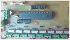
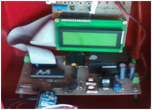
3. Presented System Block Diagram
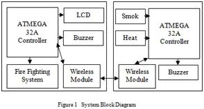
The block diagram illustrates our utilization of two ATMEGA32 microcontrollers, which establish communication between each other via a wireless module. This communication setup is employed to showcase the current state of the detectors on the LCD display.
4. Presented System Flow Diagram
Master Unit Controller Flow chart:
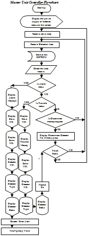
At regular intervals, the controller receives data from the slave, such as:
(A) If it receives a frame indicating a fire state, a fire message will be displayed on the screen.
(B) If it receives a frame indicating a trouble state, a trouble message will be displayed on the screen. In the event of a fire frame or trouble frame, which may occur when a detector is disconnected or connected but not functioning, the screen will show details such as the slave number, zone number, detector number, and detector status.
Slave Unit Controller Flow chart:
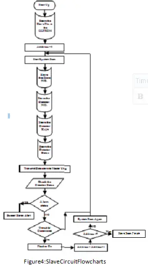
At regular intervals, the controller transmits the status of the detectors upon receiving acknowledgment from the master controller, activating the siren or flasher to indicate an alarm or trouble condition.
5. System structure and features
The initial objective of early systems was to improve property protection by promptly alerting first responders, enabling swift human intervention to minimize property damage. The design presented here involves a system that operates through a conventional detector. The output of this detector varies and provides a proportional representation of the sensory impact of fire heat and smoke. These signals are directly linked to the control unit circuit, as depicted in Figure (5).
The transmission of this information represents a digital current sent to the control panel, conveying the sensed or monitored condition of the room. Within the Slave unit, detectors periodically transmit their identification number and the corresponding zone number. By possessing the digital details of the conventional detector’s number and status, the system operates intelligently. In the event of fire or trouble, both the master and slave units promptly initiate actions, activating a siren and relays for the firefighting system after a specified delay. Otherwise, the system remains in a standby state. Additionally, the master unit’s LCD displays all relevant system events.
The controllers in both the master and slave units share several features, including (1) a high-performance, low-power AVR® 8-bit Microcontroller, (2) non-volatile program and data memories, and (3) a programming lock for software security. The proposed design incorporates a wireless module known as the ZigBee module. IEEE 802.15.4, the wireless standard employed by ZigBee, relies on PSK and allows for the utilization of two frequency bands: 868–915MHz using BPSK and 2.4GHz using OQPSK. Illustrations of the major components of the transmitter and receiver structure are presented below.
The binary data stream undergoes division into its in-phase and quadrature-phase components, each of which is subsequently modulated onto two orthogonal basis functions. In this particular setup, two sinusoids serve as the basis functions. Following this, the two modulated signals are combined, resulting in the formation of the QPSK signal. It’s worth noting the application of polar non-return-to-zero encoding.
While these encoders could be positioned before the binary data source, in this instance, they have been positioned afterward. This choice is made to highlight the distinctions between digital and analog signals within the realm of digital modulation.
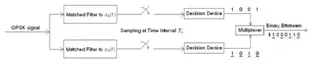
Correlators can serve as substitutes for matched filters. Each detection device employs a reference threshold value to ascertain the detection of either a 1 or 0. In QPSK, both the in-phase and quadrature channels are utilized, with each channel carrying a BSPK component [8]. The transmitted signal is given by the equation:
\[s(t) = A_b I_p T(t) \cos(2\pi f_c t + \mu) – A_b Q_p T(t) \sin(2\pi f_c t + \mu) \quad (1)\]
Here, \(b_I\) and \(b_Q\) represent the information bits on the in-phase and quadrature channels, respectively, each taking values of +1 or -1 based on the information to be transmitted. Alternatively, the transmitted signal can be expressed as:
\[s(t) = \sqrt{2} A_p T(t) \cos\left(2\pi f_c t + \mu + \tan^{-1}\left(\frac{b_Q}{b_I}\right)\right) \quad (2)\]
This representation clearly elucidates that QPSK is a form of phase shift keying. It’s worth noting that \( \tan^{-1} \left(\frac{b_Q}{b_I}\right) \) in this context should be written as \( \tan^{-1} (b_Q, b_I) \) and interpreted as a double argument function. Coherent demodulation can be independently carried out on the two channels using the receiver depicted in Figure 9.
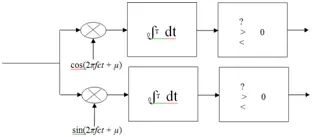
If the energy per bit (E) and the noise power spectral density (N0) remain constant, the likelihood of bit error remains unchanged compared to BPSK.
6. WirelessModule
Zigbeemodule: The establishment of wireless networks can be achieved through various RF protocols [9]. The XBee module utilized in this template, produced by MaxStream, is a ZigBee module. XBee multipoint RF modules prove advantageous in applications demanding low latency and predictable communication timing. Whether employed as a direct cable substitute for simple serial communication or as part of a more intricate hub-and-spoke network of sensors, the XBee multipoint RF module facilitates quick and robust communication in point-to-point, peer-to-peer, and multipoint/star configurations, maximizing wireless performance and simplifying development. The over-the-air data rate for the XBee is 250 kbit/s, but due to UART limitations, its maximum speed is 115.2 kbit/s. The primary reasons for selecting the XBee include (1) straightforward out-of-the-box features (Standard UART) and (2) a reasonable price.
ZigBee, constructed on the IEEE 802.15.4 standard and adhering to strict IEEE guidelines, ensures long-term sustainability and reliable operation. Developed to meet the market’s demand for a cost-effective, standards-based wireless network supporting slow data rates, low power consumption, security, and reliability [10], ZigBee relies on the underlying IEEE 802.15.4 Physical (PHY) and MAC layers for packet data transport. The MAC layer employs Carrier Sense Multiple Access with Collision Avoidance (CSMA-CA), similar to WLANs. While ZigBee essentially resides at the same layer as the TCP/IP protocol used for Internet traffic, it is optimized for Personal Area Networks (PANs), encompassing a coordinator and one or more routers/end devices. ZigBee defines two device types: Full Function Device (FFD) and Reduced Function Device (RFD). FFDs can serve as network coordinators or regular devices, communicating with any other device, while RFDs are designed for simpler applications and can only communicate with FFDs.
ZigBee supports three types of networks: 1) Star network, where devices communicate solely via the PAN coordinator; 2) Cluster Tree network, with routers facilitating data and control message movement hierarchically; and 3) Mesh network, allowing full peer-to-peer communication [11]. Zigbee, a new short-range, low-power, low-rate wireless networking protocol, complements high data rate technologies like WLAN, opening doors for various applications. Operating in three bands—the 2.4 GHz band with a maximum rate of 250 kbps, the 915 MHz band with a data rate of 40 kbps, and the 868 MHz band with a data rate of 20 kbps [12].
7. WirelessSensorNetwork
Wirelesssensornetworks(WSNs)
on efficient Medium Access Control (MAC), which ensures a successful and reliable communication process. The implementation of wireless technologies offers a cost-effective solution, particularly for maintenance and installation, with a particular emphasis on building refurbishment and retrofitting. Wireless Sensor Networks (WSN) prove highly suitable for facilitating communication among detectors in a fire alarm system [2]. The deployment of wireless sensor networks in the realm of fire emergency detection and response within building environments represents a novel application area. In such critical settings, the timely acquisition, detection, and response of data are crucial for the effective automation of building systems [1].
Wireless sensor networks encounter two primary challenges in the context of sensing and reporting on a spreading fire. Firstly, the need to rapidly report large volumes of data to a central sink or base station arises, demanding an increased rate of sensing that necessitates more frequent data transmission than normal operations [1]. Secondly, as the fire spreads, the network itself may degrade, leading to the blocking of links and the loss of individual nodes [1]. This scenario renders stored routing information invalid, resulting in potential disconnection of entire network areas. To address these issues, we explore three techniques for the operation of an in-building sensor network during a fire: real-time robust routing, a routing protocol capable of leveraging transient connectivity provided by firefighters, and traffic-adaptive Medium Access Control (MAC) [1].
In Wireless Sensor Networks (WSNs), the Medium Access Control (MAC) function is particularly vital for ensuring successful communication. During fire detection situations, the efficacy of WSN communication hinges on an efficient MAC implementation, which oversees flow control through acknowledgments and retransmissions. Additionally, MAC is responsible for data validation, synchronization, and providing services to the upper layers of the network [1].
Offering an economical solution, particularly in the realms of maintenance, installation, building refurbishment, and retrofitting, is easily achievable through the utilization of wireless technologies. Wireless Sensor Networks (WSN) prove highly suitable for facilitating communication among detectors in a fire alarm system [2]. The application of wireless sensor networks for fire emergency detection and response in building environments presents a novel and crucial domain. In such critical scenarios, the swift acquisition of data, timely detection, and prompt response are essential for effective building automation [1].
Deploying wireless sensor networks for sensing and reporting on a spreading fire encounters two primary challenges. Firstly, the system needs to promptly report large volumes of data to a central sink (also known as the base station). This requires an increased sensing rate, leading to more frequent data transmissions than normal operations [1]. Secondly, the network itself faces degradation as the fire spreads, causing blockages in links and the loss of individual nodes [1]. Stored routing information quickly becomes obsolete, and entire sections of the network may become disconnected. We explore three techniques for operating an in-building sensor network during a fire: real-time robust routing, a routing protocol capable of leveraging transient connectivity provided by firefighters, and traffic-adaptive Medium Access Control (MAC) [1]. The MAC ensures flow control through acknowledgments and retransmissions, handling data validation, synchronization, and providing services to the upper layers in Wireless Sensor Networks (WSNs) [1].
In the context of WSNs, Medium Access Control (MAC) plays a pivotal role in ensuring successful communication [1]. During fire detection situations, the effective communication of the WSN relies on a reliable communication protocol for transporting detector status messages to the Master Unit Controller or base station.
8. System results
The initiation devices, such as conventional smoke, heat, gas, or flame detectors, detect the presence of smoke, temperature, or flames in a designated zone area. The first microcontroller records the status of the detectors and transfers this data to the second microcontroller. Consequently, the slave unit controllers either transmit or receive actions determined by the master unit controller through the Zigbee module. The primary objective of the suggested system lies in achieving intelligent functionality through wireless communication with conventional detectors. Our case study involves the integration of Conventional Fire Alarm System Devices with Wireless Communication Signals.
When an application requires communication in a point-to-point or point-to-multipoint manner, IEEE 802.15.4 can efficiently manage communication between these devices and is simpler to implement than attempting to use a module with ZigBee firmware for the same purpose. ZigBee becomes necessary when incorporating a repeater or utilizing mesh networking functionality. The performance results for our presented wireless fire alarm system using conventional detectors are outlined in Table 1.
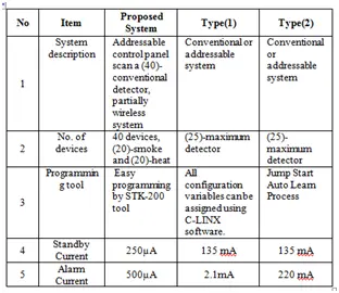
Upon comparing our design with any other marketing system, it becomes evident that it is a distinctive wireless fire alarm system employing conventional detectors characterized by the lowest total power dissipation.
9. Conclusion
Contemporary wireless networks comprise a vast array of cost-effective devices interconnected through low-power wireless communication. The advancements in wireless communication, networking, and wireless sensor network technology are anticipated to wield a substantial influence on our lives in the twenty-first century [9]. This paper introduces the design and implementation of a fire alarm system controlled by two ATMEGA32 microcontrollers. These microcontrollers establish communication with each other through both wired and wireless channels, aiming to diminish the costs, expenses, and labor associated with the fire alarm system. Conventional devices are utilized to facilitate communication between initiation devices (Detectors) and the first ATMEGA32 microcontroller through wired means, while wireless communication is employed between the second ATMEGA32 controller.
The intelligent aspect lies in the system’s ability to automatically recognize the detector’s address and type. This not only streamlines the operation but also significantly reduces the overall cost of the fire alarm system unit. All suggested system components, including detectors, controllers, and wireless modules, are readily available at any time and can be easily programmed.
- What components are used in the wireless fire alarm system?
The system uses ATMEGA32 microcontrollers, ZigBee modules (XBEE), heat detectors, smoke detectors, LCDs, sirens, relays, and flashers. - How do the Master and Slave units communicate?
Communication between the Master and Slave units utilizes a wireless transmission line employing ZigBee modules. - Does this system offer lower power consumption than existing systems?
Yes, upon comparing the design with existing marketing systems, it exhibits the lowest total power dissipation. - Can the system identify specific detector issues?
Yes, if a trouble frame occurs, the screen displays details such as the slave number, zone number, detector number, and detector status. - What wireless standard does the ZigBee module use?
The ZigBee module is constructed on the IEEE 802.15.4 standard. - What types of networks does ZigBee support?
ZigBee supports Star, Cluster Tree, and Mesh network configurations. - Is the system suitable for retrofitting buildings?
Yes, wireless technologies offer an economical solution particularly for building refurbishment and retrofitting. - How does the system handle fire or trouble conditions?
In the event of fire or trouble, both master and slave units activate a siren and relays after a specified delay. - What is the primary advantage of this design over conventional systems?
The design transforms a conventional system into an intelligent wireless one that minimizes overall costs and maintenance requirements.