Overview
The SmartBlinds system uses a microcontroller to control the angle of a set of miniblinds used at home, in the classroom, or on the job. Using SmartBlinds, a user can more effectively control the light coming into the room, or have an alarm that opens at a specified time.
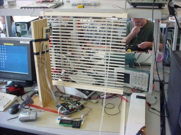
We’ve noticed that despite the convenience of owning miniblinds, we were frequently too lazy to get up to adjust the angle of the blinds. So we decided to focus this project on using a microcontroller to adjust the angle of the blinds to incoming light. Using LEDs to detect light and a motor, we were able to effectively control the angle of the blinds to angle towards the direction of the incoming light.
High-Level Design
This project was chosen because of its originality. We simply decided that we did not want to do another video game project. When brainstorming, we started staring off into the room walls and began to wish that there was more sun-light in the room. Looking at the miniblinds covering the window gave us this idea. We liked the idea because turning the miniblinds is an everyday nuisance that most people can relate to. Further, we liked this project because it required a nice mix of both hardware and software. For instance, we needed to implement op-amps with filters as well as H-bridges to control the motor, as well as program a nice interface that users could enter in alarm times without having to press up and down repeatedly.
Our implementation boasts five modes of operation: timeset mode, optimize mode, updown mode, alarm mode, and privacy mode. The mode is selected by using a keypad, and the current mode and any other relevant information will be displayed on an LCD.
Operation of the system under each mode is as follows:
Optimize Mode
Most people are too lazy to leave their desk every ten minutes to adjust the blinds in their room to maximize the sunlight entering the room. As a result, the blinds stay at the same position all day, wasting valuable sunlight that could have been used by the studious individual sitting at his desk. To alleviate this problem, we propose to adjust the inclination of a set of miniblinds to admit the maximum possible amount of sunlight into the room. In optimize mode, the user doesnt have to do anything; thats the beauty of it!
UpDown Mode
In UpDown mode, the user presses two buttons on the keypad to change the angle of the blinds up or down until a desirable inclination is reached. The blinds then stay at this position until the up/down buttons are pressed again or the mode is changed. The buttons are sensitive enough in time to rotate the blinds for under a revolution.
Alarm Mode
This mode wakes the user up at a certain time. The alarm time is set using the keypad and is displayed on the LCD. The blinds immediately close when entering this state and waits for the user the input the alarm time. The user should type hhmm where hh is the hour in 24-hour format and mm is minutes. When the wakeup time is reached, the blinds open to allow light to permeate the room.
Privacy Mode
Upon setting the system to privacy mode, the blinds immediately close to prevent any peeping-toms from getting any indecent exposure!
Time Set Mode
This mode allows the user to adjust the current system time in as hhmm where hh is the hour in 24-hour format and mm is minutes.
Mode Set
The user can change the mode at any time by pressing the * key on the keypad. This will take you to a menu that displays the available modes.
One of the more interesting aspects of this project is this fact that we use green LEDs as light sensors, which detect rather than produce light. We have 3 LEDs which are angled at different positions, each connected to an op-amp / filter combination. These amplified analog signals are then processed by the analog-to-digital conversion module (ADC) in the microcontroller (MCU). Using knowledge of which LED is receiving more light, the MCU then turns the motor either backwards or forwards through an H-bridge. In order to determine how long to power the motor, we used a Hall-Effect sensor which determines how many revolutions the motor has turned. Finally, we provide a keypad and LCD as a way of changing user modes and displaying user data.
The op-amps were required because the ADC would ruin the incoming LED signal. Also, originally we planned on using software to time our signals to the motor. This proved to be too difficult to accurately change the blinds since the motor would turn at different speeds depending on the blind angle.
Software Design
We have 4 tasks in our program, each of which is triggered at different time intervals. Our main function initializes all of our variables and runs as soon as a task is triggered.
The first task is run every 30 milliseconds and is our main button debouncer which detects user input from the keypad. A debouncer prevents the MCU from interpreting a long button push as multiple button pushes (see below for our state diagram).We detected user keypad input by probing the horizontal then vertical pins of the keypad (see the hardware section). By interpreting the keys signal we were able to determine which button was pressed. In addition to this debouncer, we controlled various aspects of our modes. For instance, unless we were in alarm or time set modes, we did not want to increment our variable keycount which keeps track of the index inside the keystring array. We embedded code to display the various mode headers as well into this state. Although this made the code a little more confusing, we felt we had to debounce all commands or else users would switch from one mode to another without even knowing or seeing the menu. In this task, we also calculate the time in terms of hours and minutes. Instead of having more error checking, we simply took the mod of the numbers to create a valid time.
The second task is run every 200 milliseconds and detects the light from the LEDs in optimize mode and issues most of the commands to control the motor. The main purpose of this task is to provide functionality to the optimize mode. This task changes the ADMUX variable which changes which ADC pin it converts. It updates one of the three LEDs each time the task is called then rotates to the next LED for the next call to the task. Every three times that this task is called, it then examines the intensities of each. If the one on the bottom is greater than the other two, it begins to tilt the blinds down toward the light. The same goes for the middle and top blinds. If there is not enough light in the room it does not do anything. This task make many calls to a function called gotopos(char pos). This function keeps track of the current rotation positions variable and outputs the signal to move the motor to the desired position (in terms of rotation number). Upon changing the direction of rotation, it adds two more rotations to compensate for the give when physically changing the directions on the blind shaft. The only other interesting functionality is the alarm mode which initializes to a close positions (pos = 8), then transitions to open (pos = 4) when the time has been reached. The modes privacy, modeset, and updown are very straight forward (see the code appendix).
The third task is run every 50 milliseconds and detects input from the Hall-Effect sensor. It is basically a simple debouncer (see below) which determines the current direction and increments or decrements the rotation position variable rot as needed. We had some problems reading from the ADC but eventually realized that we needed to give the ADC some time to compute the results. We found through experimentation that we could read a consistent result after delaying for 500 microseconds.
The fourth task is run every second and displays the time and rotation data on the LCD. This task is run really slowly since we do not wish to change the display too often. This task also contains the logic to change 60 minutes into 1 hour. Since the motor only rotates at about 1 revolution per second, it made sense to display the revolutions here.
The hardest part of the software to write was the user-interface. Although it initially seemed simple, we realized that we had to record multiple button presses in time set and alarm modes while being able to switch modes at any time. We needed a button debouncer to prevent the MCU from detecting a slow push as multiple pushes of a button (see an example of a debouncer above). However, we only needed this debouncer on the time set and alarm modes but none of the other modes. In the end, we decided to create another mode called mode set which allowed the user to transition from one mode to another. The user could enter into mode set by pressing *. We also used an char array of size 4 to store the user entered time or alarm.
Hardware Design
Our SmartBlind system consists of multiple hardware systems. We constructed all of our circuit hardware on two proto-boards: one houses the keypad and LCD, and the other contains the light sensor, motor/H-Bridge, and Hall effect sensor circuits.
The keypad is used to take user input for the switching of modes, the entering of times, and the manual adjusting of blind tilt in UPDOWN mode. The keypad pictured below is the keypad we used for our SmartBlind system. Each pin corresponds to a certain row or column, and these pins are fed into port B on the Mega32. To read a button press, the most significant four bits of the port are set to input with pull-ups while the least significant four bits are set to outputs. A button press then connects one of the column pins to one of the row pins, bringing one of the inputs to zero. As a result, all of the row pins are high except for one, while the column pins are all zero. This value is stored in a variable called key. After a five-us delay, the four most significant port pins are set to outputs, and the four least significant pins are set inputs with pull-ups. The same button is still being pressed since a user cannot press and release a button in less than five microseconds. Now the connection drives one of the column pins low, and we then know which column the button press corresponds to. This value is ORed into the key variable, and this final value represents which key was pressed. (See the keypad diagram and pinout below.)

The 16×4 LCD is used to display the mode of operation (TIMESET, OPTIMIZE, PRIVACY, ALARM, or UPDOWN). It also displays the current time as well as mode-specific data. The TIMESET and ALARM modes have a field to show the time as it is being entered, and the OPTIMIZE mode shows the light values (ranging from 0 to 1) for each of the three LEDs. These values are reprinted about every second so the LCD always shows the current light values in OPTIMIZE mode.
For OPTIMIZE mode, we detect the light in the room on three green LEDs. Green LEDs, according to Prof. Land, have the best response to human visible light (since humans are most sensitive to green). Since a LED registers a voltage across its terminals when exposed to light in the direction of its bulb, we position these LEDs in different directions to get a feel for which direction the light is coming from. The output of the LEDs is then fed into an operational amplifier circuit with a low-pass filter that has a gain of five to amplify the signal before passing it to the analog-to-digital converter (ADC). The low-pass filter uses a 1uF capacitor and a 200KOhm resistor to get an RC time constant of 0.2s. Therefore, the noise is filtered out, but the signal also stabilizes quickly. Below is a circuit diagram that shows the construction of the LED/op-amp circuit. Three such circuits were used for the three LEDs in our project. Each output went to a different input (0,1,2) of port A into channel 0-2 of the ADC.
When we want to position the blinds in a different position, we use a 6V DC geared motor to turn the blind-adjustment shaft. The motor is driven by an H-Bridge that is in turn driven by two pins of port D. These two pins would be low-high to move the motor in one direction and high-low to move the motor in the other direction. Below is a diagram showing the H-Bridge and motor circuit. When D.0 = 5V and D.1 = 0V, the npn Q4 transistor is on and the pnp Q2 transistor is on while the other two transistors are off. This makes the motor spin backwards. When D.0 = 0V and D.1 = 1V, the pnp Q1 transistor is on and the npn Q3 transistor is on, while the other two transistors are off. This time, the motor spins forwards. D.0 and D.1 are both zero when we want the motor to stop, and both pins are never high at the same time; however, if such a state should occur, it would also turn the motor off. We used a seperate 6 Volt power supply for both the H-bridge and the motor.
The Hall effect sensor outputs a five-Volt signal normally and a zero-Volt signal when a magnet is close to it. The sensor is used to help determine how many times to turn the shaft at any given time. The Hall effect sensor, attached near the shaft of the motor, registers a zero-Volt pulse when a magnet on the shaft passes by it. This pulse shows when the motor shaft makes one full revolution. This value is also passed into the ADC.
Parts List:
| Parts | Quantity | Cost |
| IN4001 Diode | 4 | free |
| 1MOhm Resistor | 6 | free |
| 200KOhm Resistor | 3 | free |
| 100Ohm Resistor | 4 | free |
| 1 uF Capacitor | 3 | free |
| green LED | 3 | free |
| TIP 31 Transistor | 2 | free |
| TIP 32 Transistor | 2 | free |
| LMC7111 | 3 | free |
| Hall effect sensor | 1 | free |
| Motor (hmimotors) | 1 | free |
| Plywood | 2 | free |
| Screws | 4 | free |
| Metal bracket | 2 | free |
| LCD-87 screen (allcorp) | 1 | 11.25 |
| CAT# KP-26 Keypad (allcorp) | 1 | 5.00 |
| Miniblinds | 1 | 3.00 |
| Breadboard | 2 | 10.00 |
| Mega32 | 1 | 8.00 |
| TOTAL | 37.25 |
For more detail: SmartBlinds