Introduction
The most fitting way to explain our final project is to describe it as a smartboard replacer. Through the use of an IR camera, we read the position and movement of an IR LED to interact with a remote laptop. The systems comes with two modes, whiteboard mode and blackboard mode, which can be selected by switches. In whiteboard mode, the user can interact with a projected image to do simple things like scroll through a page or move a mouse. In blackboard mode, the user will be able to write on a blackboard and have the IR camera trace the movements and draw it on paint and save the images. The goal was to create an affordable smartboard replacement for classrooms.
High Level Design
Our system is set up in the following manner: there is a user with an IR source and a few buttons that feeds as an input to the microcontroller. The IR source movement and position is read by an IR camera while there is a wireless protocol to communicate the buttons with the microcontroller. The microcontroller will process the input data into the correct format such as position and actions to take. Then the microcontroller will send that data to the PC using serial communications. The PC will use Matlab which will control actions on the PC such as mouse movements or drawing on paint.
Rationale and Source
The idea for our final project came from a moment in lecture when Bruce Land tried to scroll on a projected image on the whiteboard. “Wouldn’t it be great if you didn’t have to walk back to your laptop but could scroll literally on the projected image?”. Then a lecturer would not have to go back and forth between the board and the laptop which is running the presentation.
Logical Structure
There are three major subsystems that make up this project. The first is the user interface which consists of a 2 switches, 1 button, a few IR LEDs, and a wireless transmitter. The buttons and switches control the actions that the user wants to perform. This information is sent to the second subsystem, the microcontroller. The microcontroller takes in the input from the user interface and inputs from the IR camera that senses the user with the IR LEDs. The microcontroller does some processing and then sends the information to PC and Matlab, our third subsystem, using a USB serial interface. Matlab takes in the information and actually does the actions we want on the PC and by extension onto the projector.
Hardware/Software Tradeoffs
The majority of our projects runs off software. This is because the software is what calculates the inputs from the user and IR camera and figures out the actions that we need to take. This calculation of the inputs to required data to Matlab is not something that we would try to do in hardware since the data easy for the microcontroller to convert through software. However, a big challenge for this project was to get the hardware working. Although it looks simple, it is very difficult to get the IR camera to function due to its very specific needs. Furthermore, since there is no datasheet available, we have to rely on forum informaton and manual debugging. And finally, since it is not possible to buy the IR camera separately, we always have to scavenge an IR camera from a Wiimote. It’s almost impossible to check if the IR camera has a problem or whether it’s the code that has a problem.
Standards
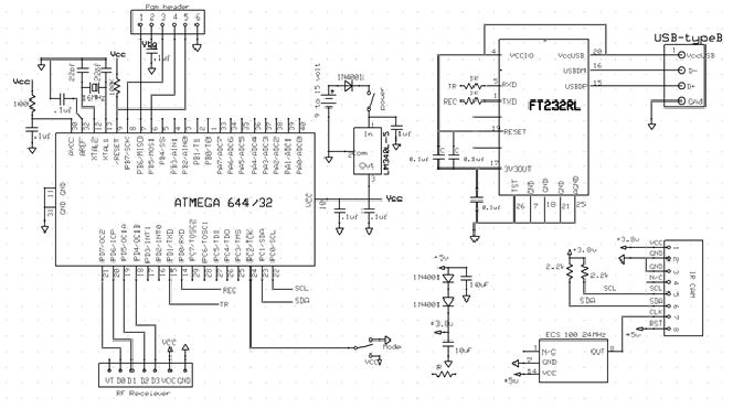
In our project we use I2C to communicate from the IR camera to the microcontroller and USART from the microcontroller to Matlab. The wireless module works at 433MHz which many low power devices use.
Copyrights and Patents
Much of our information on the IR camera comes from sources on the internet, the originator being Kako. We also use some information from wiibrew.org. To do some of the Matlab to microcontroller communication, we refer to Hand-Motion Chess from SP2013, and by extension of Bruce’s bird song code.
Software
C Code
The majority of the work done on this project is through software. The software takes in the data from the IR camera and outputs it to Matlab to control the mouse movement and scrolling. To begin, we started with the most difficult part of this project: get a working I2C communication between the IR camera and the microcontroller.
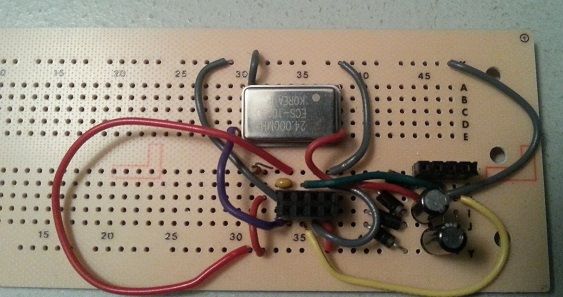
I2C is made up of 4 wires: Vcc, Gnd, SCK(clock) which runs around 100-400kHz, and SDA(data) the line which data transmits on. The camera also required another input of 24MHz to run the actual camera. To simplify our lives and not write our own protocol, we instead started with Peter Fleury’s I2C code for ATMEGA. The code uses the built in TWI (two wire interface), the hardware ATMEL version of I2C. It defines important function such as start, write data, and read data by setting the TWI register values.
However, this did not seem to work well for us and it seemed to write incorrect values and did not read the values from the camera correctly. It could have been a timing issue, but we could not make it work as some others groups did. One conjecture as to why it did not work is that the the I2C timing was incorrect. As the example code was meant for a specific chip, we might have required a different I2C clock rate. We did changing the frequency and some of the parameters in the I2Cmaster file, but they did not work. We did see data of some sort being transmitted, but it was garbage. A second reason that this could have been wrong is that the I2C protocol on the camera needed some specific way of handling writes and reads. The I2Cmaster file we actually used was designed to look at the specific registers in the camera and confirm we were writing. A third reason, and the one we believe to be the problem is I2C rep start. The use was to switch from a write to a read correctly since to read an output we must first declare where we are reading from by writing the address. The difference in the second I2Cmaster file is that it did not have a rep_start function but just called start again. This might encapsulate the previous 2 reasons and is why is the favored explanation for why Peter Fleury’s I2Cmaster failed.
Instead, we used an I2C file from Kako. It also runs the I2C protocol, but is tailored to communicating with the IR camera, specifically checking registers that are in the camera when issuing a read or write command. We had to slightly adjust the code to fit our Atmega TWI interface to make this work. Since there is contradicting and very little information on the actual I2C protocol for Wiimote Camera, most of our time was spent debugging this protocl. We extensively used the oscilloscope to snoop the transmitting and receiving data and make sure it was valid.
The second part of the software was to figure out serial communication from the microcontroller to the PC and Matlab. As stated in Copyright and Patents, we derived the basic communication from Hand-Motion Chess, specifically since we wanted to know about timing. When Matlab sends the command, we wanted to know if the microcontroller code has any noticeable delay that we would have to calculate and compensate for in Matlab from using fprintf to send data over the serial port. We found that it did not and that the microcontroller was fast enough to make it a needless concern.
The final part was to process inputs from the camera and user and send to Matlab the correct action variables and values needed to function peroperly. The overall process begins with the microcontroller constantly processing and preparing data including mode, action, and X-Y coordinates. Of course only the appropriate data should be sent, and this is done through if statements to choose the corresponding data to the action. If no valid actions are given, we send a fourth action to indicate no valid actions exists and Matlab should do nothing. All of the modes and actions are sent as integer values.
Before the if statements, we read the IR camera data and the mode from the user as these are data that is always sent to Matlab. After the reading is the if-elseif-elseif-else statement. The if statement is the priority action, left click. This is the most important action in our system and is given priority. The other actions are put in an arbitrary order as they are not as important. The code ends with reading from the UART for the start bit and then a fprintf statement to send the data to Matlab. This is all done in an infinite while loop.
Matlab Code
On the Matlab side, we start by clearing any serial connections that are being used and using Matlab’s serial function we set up a COM serial connection. Then we set up initializations to run the code such as variables and importing java classes for Robot, KeyEvents, and MouseEvents. The bulk of the Matlab code comes after which involves the reading and processing.
we use the fprintf and fscanf to communicate with the microcontroller over the serial port. We start by sending a start bit, s, and immediately try to read the incoming data. Because the microcontroller is so fast, we do not have to do any timing and try to pause for the microcontroller to do it’s calculations. Then a while loop looks at the data from the microcontroller and performs the appropriate action.
Here our first use of the data happens. We take in the X-Y coordinate data and disregard 1/16 of all the data on the border of the visual field. This is because the borders have a lower level of accuracy that causes incorrect readings. This was revealed to us during testing. For example, if we do not disregard 1/16 of the data, then X close button on a window is in the top right corner of the screen. This translates to the top right corner of the vieweing area for the IR camera. However, this area is very sensitive and thus it is very difficult to accurately move your hand there. Therefore, by disregarding the borders, we can increase the accuracy of our movements. As for the scrolling, we used a very simple and efficient method. We divided the viewing area into three areas. If the user moves the pointer to the upper third of the viewing area, Matlab will continue scrolling up. Similarly, it will continuously scroll downward for the bottom third of the viewing area. The middle third area is for no scrolling. This is very simple code yet very efficient in scrolling because you can easily move your hands accordingly to scroll up or down.
The rest of the code is broken up into nested if statements, the first layer looking at which mode we are working in and the second layer deciding the correct action to take in the mode. The microcontroller also can send a third mode for when there is no valid action to take. KeyEvents are to do shortcut commands to control some functions while MouseEvents do scrolling, moving, and clicking with the cursor. In particular, to do scrolling we check whether the IR LED is in the top 1/3 or lower 1/3 visual field, including the discarded border. If it is found in this region it will scroll in the direction that the remote can be found. There are delay functions so that the user can easily stop scrolling when the correct page appears.
Testing Microcontroller
Testing the microcontroller comprised mainly of using the PuTTy console to look at the data we were calculating and receiving from the user. The data being sent to Matlab was simple integers so we only had to make sure the calculated outputs were correct and updated properly. A few points of difficulty encoutered came from reading the IR camera properly and finding that our B.2 port did not have a good pull-up resistor which made the microcontroller unable to get proper data.
We also tested our wireless transmitter and receiver. The way we approached this was to start with one button from the transmitter to a pin on the receiver. If the microcontroller received a high signal from the receiver it would light up an LED and turn it off as if no information came through. This allowed us to seperately test the wireless module without needing to use the microcontroller.
Testing Matlab
Testing the Matlab code took the less precise form of sending fake data of actions we want and seeing if the right actions are taken. We built up the Matlab code to do simple actions autonomously one time then moved on to a finite loop of a certain action, then a while loop of single actions. Last was to put in if statements to do the proper actions. This was to make sure that the Matlab code worked in isolation.
Latency and Speed
Our latency is quite low for this project and we wanted to quantify this to an order of magnitude if not an exact value. Unfortunately, the speed of the program itself is too fast for a human to tell. But using Bruce Land’s suggestion we used the tic and toc function in matlab to get an approximate measurement. This is accurate enough because the system depends on matlab to send a request to the microcontroller, recieve and do some processing, and then perform a visible action we encoded in one loop.
We also tested the latency of our wireless transmitter and reciever. This was an acceptable latency but noticeable to a human. We made a quick estimate that it was better than 200ms since we could not notice any latency at all. To get a better measurement, we again used matlab and timed how long it took for the first change to occur when pressing a button.
Hardware
Client Side
The following is a description of the hardware aspect of our project for the client side. The client side consists of the IR camera, the microcontroller, and a RF receiver. All of these are connected together and then the microcontroller connects to the PC using serial connection.
Parts List:
| Part | Vendor | Cost/Unit | Quantity | Total Cost |
|---|---|---|---|---|
| Atmega 1284 | Lab Stock | $5 | 1 | $5 |
| PC Board | Lab Stock | $4 | 1 | $4 |
| White Board | Lab Stock | $6 | 1 | $6 |
| Solder Board | Lab Stock | $2.50 | 1 | $2.50 |
| header pins | Lab Stock | $0.05 | 52 | $2.60 |
| Power Supply | Lab Stock | $5 | 1 | $5 |
| 9V Battery | $0 | 1 | $0 | |
| Wii Pixart Camera | Amazon | $15.99 | 1 | $15.99 |
| 24 MHz Clock | Digikey | 2.63 | 1 | 2.63 |
| Wireless TX/RX | Robotshop | 18.95 | 1 | 18.95 |
| Push Buttons | Lab Stock | $0 | 1 | $0 |
| Switches | Lab Stock | $0 | 3 | $0 |
| Wires,Resistors,Capacitors | Lab Stock | $0 | many | $0 |
| TOTAL: | $62.67 |
For more detail: Smartboard Replacement interactor Using Atmega1284