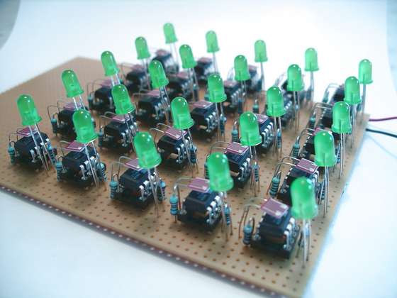
Have you ever asked yourself how do hundreds and thousands of fireflies are able to synchronize themselves? How does it work, that they are able to blink all together without having a kind of boss firefly?
This instructable gives a solution and shows how this synchronization can be achieved.
I have always been fascinated by self organization of insects. A couple of years ago I wrote a Java-Applet that simulates a square of thousands of fireflies. It worked well and was fun to watch. This time I have done it in hardware.
Credits for inspirations goes to Keso and his Jar of fireflies http://www.instructables.com/id/E7U5HYMSVIEWP86SAL/.
Any comments or corrections are welcome.
Update 2008-09-12: There is a new version of the fireflies online at Synchronizing Firefly Howto. It has a custom PCB for every firefly. And you can buy a kit at the Tinker Store.
Here is the video:
Step 1 How it works
And what is it good for? It is used to attract other specimen. With all the blinking in sync it is much easier to find a partner.
One of the easiest algorithm to explain this behaviour goes like this: You have a value that holds the power to flash. As time passes this power will slightly raise. If the power reaches a certain level, the firefly flashes and the power is consumed. The rate at which the power raises is nearly the same for all fireflies. So they have the same frequency but not the same point in time to flash.
While slowly charging with power the firefly is able to detect a flash of another firefly nearby. It adds then a higher value to its power value. Some kind of power boost, if you wish. That means the next flash will occur earlier than the one before. And next one even earlier, until these two are flashing exactly at the same point in time and with the same speed.
You can find more on this algorithm e.g. here:
Firefly Synchronization Ad Hoc Networks
The Hardware
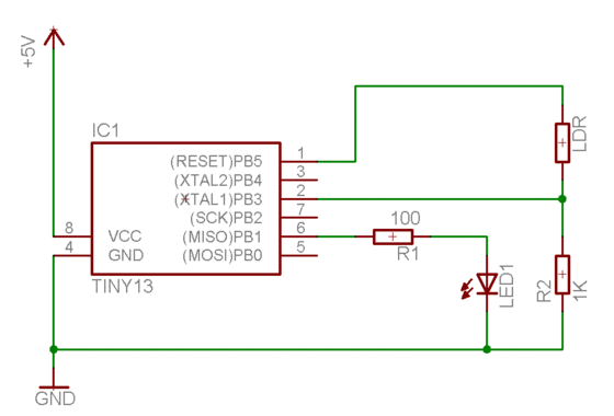
I decided to use my previous instructable (Programmable LED) as starting point. It consists of a microcontroller, an LED and an Light Dependent Resistor (LDR). That should be enough to simulate a simple firefly. It is able to flash, to see and to count.
I just had to modify the program and the orientation of the LED and the LDR. LED and LDR must been placed in a way that one firefly circuit is able to interfere with another. So one LDR must be able to “see” the LED of another firefly. And it should not only see one neighbour but more. That can be done by letting the LED and the LDR pointing up from the ground and use some white paper to reflect the flashes.
Step 2 Materials and Tools
- 25 x 1K Ohm resistor
- 25 x 100 Ohm resistor
- 25 x LDR (Light Dependent Resistor), e.g. M9960
- 25 x LED, 1.7V, 20mA (reg, green, blue, what ever you like)
- 25 x ATtiny13, 1KB flash RAM, 64 Bytes RAM, 64 Bytes EEPROM
- 25 x sockets
- prototyping board
- wire
The cost for one firefly should be about 1.50 Euro if you get some rabate when ordering in larger numbers.
The sockets are only neccessary, if your programs are buggy. If you feel confident with your development skills, you can spare them. 😉
You can surely replace the ATtiny chip with any other microcontroller as PIC, PICAXE or BasicStamp to name a few. Just take the smallest and cheapest you can get. I go with Atmel as I had the programmer already and my first project with a ATtiny13 worked just fine.
Tools
- Soldering iron
- Solder wire
- Breadboard
- AVR programmer
- 5V Power supply or
- 4 AA rechargeables
Software
- WinAVR
Step 3 The Circuit
The circuit is not very complicated as you see. The LED is connected to an I/O port, the LDR to an ADC port (to enable seeing light differences, not only black and white).
For more details on the circuit see here: Programmable LED.
With my last instructable I got some comments about using the LED as light sensor. Yes, using the LED as a sensor. I gave it a try and it basically worked, I could detect light and shadow.
But I was not able to do use it in a more analog way as I was using the LDR before. At least I was not able.
For more Detail: Synchronizing Fireflies using Microcontroller ATtiny13


