Summary of The Atmel-ICE Debugger
The Atmel-ICE is a versatile development tool for debugging and programming Atmel AVR and SAM microcontrollers. It supports multiple interfaces like JTAG, SWD, PDI, and debugWIRE across various families including UC3, XMEGA, megaAVR, tinyAVR, and ARM Cortex-M devices. The tool offers high-speed USB 2.0 connectivity, ITM serial trace capture, and operates within a target voltage range of 1.62V to 5.5V. It requires Atmel Studio 6.2 or later and connects via standard HID or optional USB drivers.
Parts used in the Atmel-ICE:
- Atmel-ICE unit
- USB cable (1.8m, high-speed, micro-B)
- Adapter board with adapters for 50-mil AVR, 100-mil AVR/SAM, and 100-mil 20-pin SAM connections
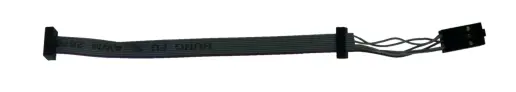
- IDC flat cable with a 10-pin 50-mil connector and a 6-pin 100-mil connector
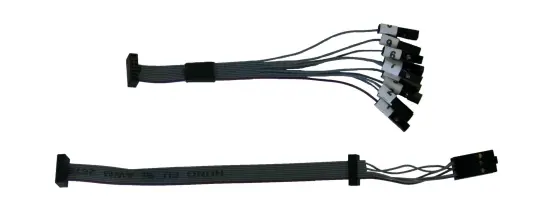
- 50-mil 10-pin mini squid cable with 10 x 100-mil sockets
- 100-mil 10-pin JTAG/SWD adapter
- 100-mil 20-pin SAM JTAG/SWD adapter
- 50-mil 6-pin SPI/debugWIRE/PDI/aWire adapter
1. Introduction
1.1 Introduction to the Atmel-ICE
Atmel-ICE is a highly capable development tool designed for debugging and programming Atmel SAM and Atmel AVR microcontrollers based on ARM Cortex-M architecture. It provides On-Chip Debug capability and supports various interfaces and families of microcontrollers, including:
- Programming and on-chip debugging of all Atmel AVR UC3 microcontrollers through both JTAG and aWire interfaces.
- Programming and on-chip debugging of all AVR XMEGA family devices via both JTAG and PDI 2-wire interfaces.
- Programming (JTAG and SPI) and debugging of all AVR 8-bit microcontrollers with OCD support through either JTAG or debugWIRE interfaces.
- Programming and debugging of all Atmel SAM ARM Cortex-M based microcontrollers using both SWD and JTAG interfaces.
- Programming (TPI) of all Atmel tinyAVR 8-bit microcontrollers with support for this interface.”

In summary, Atmel-ICE serves as a versatile tool that offers comprehensive support for programming and debugging a wide range of Atmel microcontrollers, enabling developers to work efficiently with different interfaces and microcontroller families.
1.2 Atmel-ICE Features
Fully compatible with Atmel Studio, the Atmel-ICE development tool offers extensive support for programming and debugging various microcontrollers. Here are the key features:
- Supports programming and debugging of all Atmel AVR UC3 32-bit microcontrollers.
- Supports programming and debugging of all 8-bit AVR XMEGA devices.
- Supports programming and debugging of all 8-bit Atmel megaAVR and tinyAVR devices with OCD.
- Supports programming and debugging of all Atmel SAM ARM Cortex-M based microcontrollers.
- Target operating voltage range: 1.62V to 5.5V.
- Draws less than 3mA from the target VTref when using the debugWIRE interface, and less than 1mA for all other interfaces.
- Supports JTAG clock frequencies from 32kHz to 7.5MHz.
- Supports PDI clock frequencies from 32kHz to 7.5MHz.
- Supports debugWIRE baud rates from 4kbit/s to 0.5Mbit/s.
- Supports aWire baud rates from 7.5kbit/s to 7Mbit/s.
- Supports SPI clock frequencies from 8kHz to 5MHz.
- Supports SWD clock frequencies from 32kHz to 2MHz.
- Features a USB 2.0 high-speed host interface.
- Offers ITM serial trace capture at up to 3MB/s.
- Supports a 10-pin 50-mil JTAG connector with both AVR and Cortex pinouts. The standard probe cable is compatible with AVR 6-pin ISP/PDI/TPI 100-mil headers as well as 10-pin 50-mil headers. An adapter is available to support 6-pin 50-mil, 10-pin 100-mil, and 20-pin 100-mil headers. Various kit options are available, offering different cabling and adapters.”
In summary, Atmel-ICE provides comprehensive compatibility and support for a wide range of microcontrollers, offering a variety of features and options to facilitate programming and debugging tasks.
1.3 System Requirements
To use the Atmel-ICE unit, it is necessary to have Atmel Studio version 6.2 or a later version of the front-end debugging environment installed on your computer.
To establish a connection, the Atmel-ICE unit should be linked to the host computer using either the provided USB cable or a certified USB-micro cable.
2. Getting Started with the Atmel-ICE
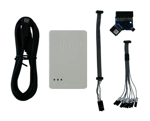
2.1 Full Kit Contents
The Atmel-ICE full kit includes the following components:
– Atmel-ICE unit
– USB cable (1.8m, high-speed, micro-B)
– Adapter board featuring adapters for 50-mil AVR, 100-mil AVR/SAM, and 100-mil 20-pin SAM connections
– IDC flat cable with a 10-pin 50-mil connector and a 6-pin 100-mil connector
– 50-mil 10-pin mini squid cable with 10 x 100-mil sockets
In summary, the Atmel-ICE full kit consists of the Atmel-ICE unit itself, along with various cables and adapters for different types of connections.
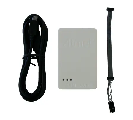
2.2 Basic Kit Contents
The Atmel-ICE basic kit includes the following components:
– Atmel-ICE unit
– USB cable (1.8m, high-speed, micro-B)
– IDC flat cable with a 10-pin 50-mil connector and a 6-pin 100-mil connector”
In summary, the Atmel-ICE basic kit consists of the Atmel-ICE unit, along with a USB cable and an IDC flat cable for connecting to different types of connectors.
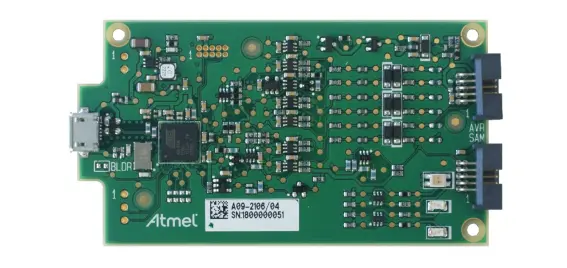
2.3 PCBA Kit Contents
The Atmel-ICE PCBA kit includes the following item:
– Atmel-ICE unit without plastic encapsulation”
In summary, the Atmel-ICE PCBA kit consists of the Atmel-ICE unit without the plastic enclosure.
2.4 Spare Parts Kits
The following spare parts kits are available:
● Adapter kit
● Cable kit
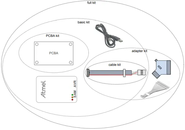
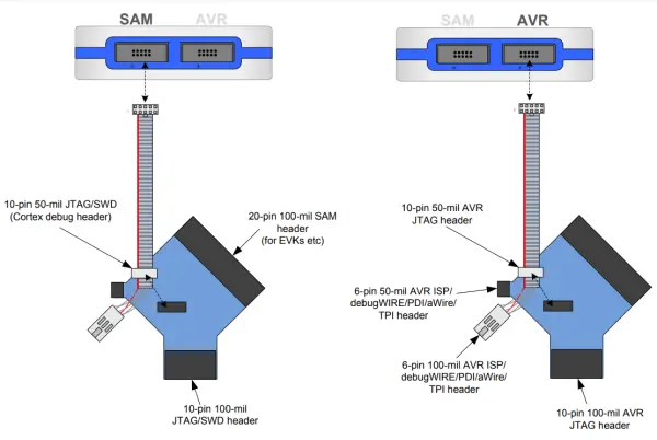
2.5 Kit Overview
The Atmel-ICE kit options are shown diagrammatically here:
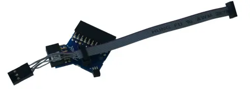
2.6 Assembling the Atmel-ICE
The Atmel-ICE unit is shipped with no cables attached. Two cable options are provided in the full kit:
● 50-mil 10-pin IDC flat cable with 6-pin ISP and 10-pin connectors
● 50-mil 10-pin mini-squid cable with 10 x 100-mil sockets
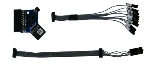
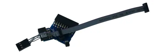
In most cases, the 50-mil 10-pin IDC flat cable can be utilized for various connections. It can be connected directly to its native 10-pin or 6-pin connectors, or it can be connected via the adapter board. The adapter board includes three adapters on a small printed circuit board assembly (PCBA), which are as follows:
– 100-mil 10-pin JTAG/SWD adapter
– 100-mil 20-pin SAM JTAG/SWD adapter
– 50-mil 6-pin SPI/debugWIRE/PDI/aWire adapter
In summary, the kit includes a versatile 50-mil 10-pin IDC flat cable that can be used with different connectors, along with an adapter board featuring three adapters for various connections.
The 6-pin ISP/PDI header is included as part of the 10-pin IDC cable, and it can be removed if not needed.
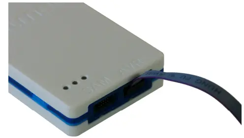
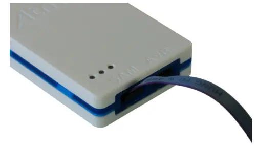
To assemble the Atmel-ICE unit in its default configuration, connect the 10-pin 50-mil IDC cable to the unit following the instructions below. Ensure that the cable is oriented correctly, with the red wire (pin 1) aligned with the triangular indicator on the blue belt of the enclosure. The cable should be connected upward from the unit. Make sure to connect it to the port that corresponds to the pinout of your target, whether it’s AVR or SAM.
In summary, the 6-pin ISP/PDI header is included with the 10-pin IDC cable, and the assembly of the Atmel-ICE unit involves connecting the cable in the specified orientation to the appropriate port based on the target’s pinout.
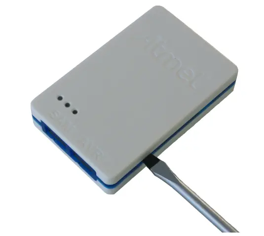
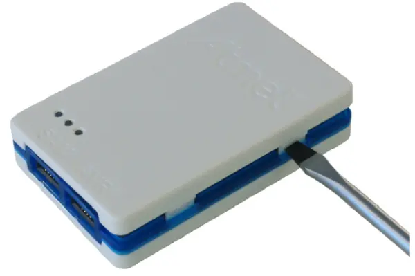
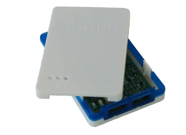
2.7 Opening the Atmel-ICE
The Atmel-ICE enclosure is composed of three distinct plastic parts: the top cover, bottom cover, and blue belt. These components are assembled by snapping them together. To open the unit, insert a large flat screwdriver into the openings in the blue belt. Apply some inward pressure and twist gently. Repeat this process for the other snapper holes, and the top cover will detach and come off.
In summary, the Atmel-ICE unit’s enclosure comprises three plastic components that can be easily opened by following the described procedure using a screwdriver.
To close the unit again, simply align the top and bottom covers correctly, and press together firmly.
2.8 Powering the Atmel-ICE
The Atmel-ICE is powered by the USB bus voltage and consumes less than 100mA of power. As a result, it can be powered through a USB hub. The power LED on the unit will light up when it is plugged in. When the unit is not actively engaged in programming or debugging, it enters a low-power consumption mode to conserve the computer’s battery. It’s important to note that the Atmel-ICE cannot be powered down; it should be unplugged when not in use.
In summary, the Atmel-ICE relies on the USB bus voltage for power and can be conveniently powered through a USB hub. It enters a low-power mode when not actively used to preserve the computer’s battery, and it should be disconnected from the power source when not in use.
2.9 Connecting to the Host Computer
The Atmel-ICE primarily communicates through a standard HID (Human Interface Device) interface, eliminating the need for a special driver on the host computer. However, to utilize the advanced data gateway functionality of the Atmel-ICE, it is necessary to install the USB driver on the host computer. This driver is automatically installed when you install the free front-end software provided by Atmel. For further information or to download the latest front-end software, please visit the Atmel website at www.atmel.com.
To establish a connection, the Atmel-ICE should be connected to an available USB port on the host computer using the provided USB cable or a suitable USB certified micro cable. The Atmel-ICE incorporates a USB 2.0 compliant controller, enabling it to operate in both full-speed and high-speed modes. For optimal performance, it is recommended to directly connect the Atmel-ICE to a USB 2.0 compliant high-speed hub on the host computer using the provided cable.
In summary, the Atmel-ICE utilizes a standard HID interface for communication and does not require a specialized driver. However, for advanced functionality, installing the USB driver through the provided front-end software is necessary. The Atmel-ICE should be connected to a USB port on the host computer using the provided cable for optimal performance.
2.10 USB Driver Installation
2.10.1 Windows
When installing the Atmel-ICE on a computer running Microsoft® Windows®, the USB driver is loaded when the
Atmel-ICE is first plugged in.
3. Connecting the Atmel-ICE
3.1 Overview: Connecting to AVR and SAM Target Devices
The Atmel-ICE probe features two 50-mil 10-pin JTAG connectors located on the front of the tool’s enclosure. These connectors are electrically connected but follow different pinouts: the AVR JTAG header and the ARM Cortex Debug header. It is important to choose the appropriate connector based on the pinout of the target board rather than the type of target MCU. For instance, if a SAM device is mounted in an AVR STK600 stack, the AVR header should be used.
The Atmel-ICE kits offer various cabling and adapters to accommodate different connection requirements. An overview of the available connection options is provided.
In summary, the Atmel-ICE probe provides two 50-mil 10-pin JTAG connectors, each with a different pinout for AVR and ARM Cortex targets. The selection of the connector should be based on the target board’s pinout. Additionally, the Atmel-ICE kits offer a range of cabling and adapters to support different connection needs.
3.2 Connecting to a JTAG Target
The Atmel-ICE probe features two 50-mil 10-pin JTAG connectors located on the front of the tool’s enclosure. Both connectors are electrically connected but follow different pinouts: the AVR JTAG header and the ARM Cortex Debug header. It is important to choose the appropriate connector based on the pinout of the target board, regardless of the target MCU type. For instance, if a SAM device is mounted in an AVR STK600 stack, the AVR header should be used.
The recommended pinout for the 10-pin AVR JTAG connector can be found in Figure 4-2, titled ‘AVR JTAG Header Pinout’ on page 20.
The recommended pinout for the 10-pin ARM Cortex Debug connector can be found in Figure 4-3, titled ‘SAM JTAG Header Pinout’ on page 20.
In summary, the Atmel-ICE probe provides two 50-mil 10-pin JTAG connectors with different pinouts for AVR and ARM Cortex targets. The appropriate connector should be chosen based on the pinout of the target board, and the recommended pinouts can be found in the provided figures.
Direct connection to a standard 10-pin 50-mil header
To connect to a board that supports the 50-mil 10-pin JTAG header, use the provided 50-mil 10-pin flat cable. The AVR connector port on the Atmel-ICE should be used for headers that follow the AVR pinout, while the SAM connector port should be used for headers that adhere to the ARM Cortex Debug header pinout.
The pinouts for both 10-pin connector ports are displayed below.
In summary, the 50-mil 10-pin flat cable included in some kits should be used to connect to a board with the corresponding header. The AVR connector port on the Atmel-ICE is suitable for AVR pinout headers, while the SAM connector port is designed for ARM Cortex Debug header pinout headers. The specific pinouts for each connector port are provided.
Connection to a standard 10-pin 100-mil header
To connect to 100-mil headers, a standard 50-mil to 100-mil adapter should be used. This can be achieved by using the included adapter board available in some kits. Alternatively, for AVR targets, the JTAGICE3 adapter can also be used.
In summary, to connect to 100-mil headers, a 50-mil to 100-mil adapter is required. The included adapter board in some kits can serve this purpose, or the JTAGICE3 adapter can be used specifically for AVR targets.
Source: The Atmel-ICE Debugger
- What microcontroller families does the Atmel-ICE support?
It supports Atmel AVR UC3, AVR XMEGA, AVR 8-bit, tinyAVR, and Atmel SAM ARM Cortex-M based microcontrollers. - How do I connect the Atmel-ICE to a host computer?
Connect it using the provided USB cable or a certified USB-micro cable to a USB port on the host computer. - Does the Atmel-ICE require special drivers on Windows?
No, it uses a standard HID interface, but the USB driver must be installed for advanced data gateway functionality. - Can the Atmel-ICE be powered through a USB hub?
Yes, it draws less than 100mA from the USB bus voltage and can be powered through a USB hub. - What is the target operating voltage range for the Atmel-ICE?
The target operating voltage range is 1.62V to 5.5V. - Which software version is required to use the Atmel-ICE?
You need Atmel Studio version 6.2 or a later version installed on your computer. - What connectors are available on the front of the Atmel-ICE probe?
It features two 50-mil 10-pin JTAG connectors with different pinouts for AVR and ARM Cortex targets. - How do I open the Atmel-ICE enclosure?
Insert a large flat screwdriver into the openings in the blue belt, apply inward pressure, and twist gently to detach the top cover.