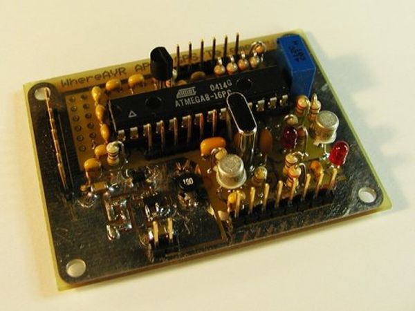
Summary of The WhereAVR using ATmega8 microcontroller
The WhereAVR is a compact, low-cost APRS tracker designed around the Atmel ATmega8 microcontroller. It features analog and digital I/O, decodes ax.25 packets for remote command reception, and interfaces directly with handheld radio speaker and mic jacks. Developed for high-altitude balloon projects, it aims for reliability, low power consumption, and ease of reproduction without requiring expensive components like the MX614. Key hardware elements include an ATmega8 MCU, a 14.7456 MHz crystal, LED indicators, a resistor ladder DAC for audio modulation, a zero-crossing comparator for audio demodulation, and a GPS signal level converter.
Parts used in the WhereAVR APRS Tracker:
- Atmel ATmega8 microcontroller
- 14.7456 MHz crystal oscillator
- LEDs for transmit and DCD indication
- Resistor digital-to-analog ladder (for audio modulation)
- Capacitors (for AC coupling signals)
- Voltage divider resistors (for comparator input and ADC scaling)
- Single transistor (for GPS receiver level conversion)
- Pull-up resistors (for input lines and transistor circuit)
Introduction
The WhereAVR is a small, lightweight, low-power, and low-cost APRS tracker with a full compliment of analog and digital I/O, as well as the ability to decode ax.25 packets. This allows for the reception of remote commands without the need for a “real” TNC. It is designed to hook directly to the speaker and microphone jacks of a handheld radio. One caveat, however, is that it currently doesn’t have a spiffy configuration utility. I’m not into windows programming yet, so that feature will have to wait. 🙂
Background Information
Inspiration for this project stemms from recent activity with a local college, The University of Alabama in Huntsville, and their high-altitude balloon projects. As part of the electrical engineering senior design course, students propose, design, and build a series of experiments which are routinely lifted to 95,000 feet and above. A common package on every flight is a “communications package”, which houses a radio, tnc, and battery pack. The TNC is a Kantronics KPC3 Plus which they use for GPS tracking and telemetry, as well as attempting to initiate a cut-down commands. The problem is that the TNC seems to be a point of contention, often causing much consternation.
Since I too enjoy ballooning, I set out to design a board which could be interfaced to a GPS receiver and used as a tracker, could also send telemetry, and possibly even decode packets in order to command actions in the payload. Naturally, it would also have applications in remote monitoring such as weather stations, repeater control, actuation in difficult to access areas, etc. My goals for the board were for it to be cheap, low power, and light, as well as dependable and easy to reproduce. Oh, one more thing… I did NOT want to have to use an MX614!
Design
Hardware Components
From the start, I knew I would be designing the board around the Atmel ATmega8. And there are several reasons for this. I have had a lot of luck using the ATmega8 in prior projects and find it easy to program. It can be programmed in-circuit, has a variety of built-in functions, and runs blazingly fast. I had also found it to operate in extreme conditions just fine – a situation I’d be subjecting it to at -30 degrees Celcius on balloon flights. Finally, the price of around $3.00 each makes them nearly disposable.
Beyond the microprocessor itself, there are a couple active components and a handful of passives. Some of the components are for direct microprocessor support – the 14.7456 MHz crystal being one. But most components are in support of additional features. They can be left off the design if the feature they support is not desired. I’ll discuss the sections of the schematic further below: I have a couple LED’s for transmit and DCD detect indication, and a level converter for the GPS receiver. There is also a section set aside for loading voltage dividers in order to scale inputs to send into the analog-to-digital converter.
Audio Modulator
Like the other trackers, I chose to generate the 1200-baud audio signal using a straightforward resitor digital-to-analog ladder. By presenting a rising or falling binary value on the port connected to the resistors, an analog signal is generated. With the proper software, you can generate nice sine-waves used to modulate the carrier transmitted by a radio. The output of this d-to-a converter is hooked to the radio microphone jack.
Audio “Demodulator”
I also wanted to decode pakcet as well, remember? To that end I chose to build a simple zero-crossing audio signal detector using the internal comparator of the ATmega8. The incomming signal is capacitively coupled to the center of a voltage divider running from power to ground. This point is then connected to one of the camarator input pins of the microprocessor. This divider is set to a voltage very near to a 1.25v bandgap reference, which is contained in the chip and is chosen via software as the other input to the comparator. In this arrangement, every time the incoming signal passes through “zero” volts, the internal comparator triggers a software interrupt. For pure sinewaves, this “zero-crossing” occurs twice per cycle. By measuring the period between interrupts, I can tell the incomming audio frequency.
GPS receiver level converter
This circuit is another straightforward design. All I do is use a single transistor as an inverter driven with the input from the GPS. Now that I think of it, I could leave out the pullup resistor as the ATmega8 has internall pullups. Oh well. 🙂
For more detail: The WhereAVR using ATmega8 microcontroller

