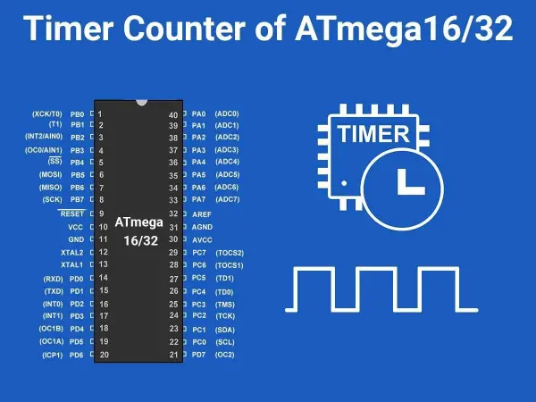
Summary of Timer in AVR ATmega16/ATmega32
Summary: The article explains timers in AVR ATmega16/ATmega32, focusing on Timer0. It describes registers (TCNTn, TCCRn, OCRn, TIFR), flags (TOVn, OCFn), waveform modes (Normal, CTC, PWM phase-correct, Fast PWM), clock prescalers, and programming steps to create delays. Example codes show generating short delays, a 10 ms delay using prescaler 1024, and enabling Timer0 overflow interrupt to toggle PORTB. Calculations for delay durations based on Fosc (8 MHz) are provided.
Parts used in the Timer0 Delay and Interrupt Examples:
- AVR ATmega16 or ATmega32 microcontroller
- 8 MHz clock source (Fosc)
- PORTB (microcontroller I/O port for output)
- Development environment with avr/io.h and avr/interrupt.h
- C compiler for AVR (to compile provided code)
- Power supply for the microcontroller
Introduction
Typically, we employ a timer/counter to generate time intervals, waveforms, or tally events. Additionally, timers are utilized for purposes such as PWM generation and event capturing.
In the AVR ATmega16 / ATmega32 microcontrollers, there are three timers at your disposal:
1. Timer0: An 8-bit timer
2. Timer1: A 16-bit timer
3. Timer2: Another 8-bit timer
These timers come with fundamental registers and flags, and they serve specific functions:
– TCNTn: Timer / Counter Register
– Each timer features a timer/counter register that initializes to zero upon reset. You can read or write values to this register, and it increments with each clock pulse.
– TOVn: Timer Overflow Flag
– Every timer has an associated Timer Overflow flag, which becomes set when the timer overflows.
– TCCRn: Timer Counter Control Register
– This register is responsible for configuring the timer/counter modes.
– OCRn: Output Compare Register
– The value in this register is compared with the content of the TCNTn register. When they match, the OCFn flag is raised.
Now, let’s delve into Timer0 to gain a better understanding of timers in the ATmega16 / ATmega32 microcontrollers.
Timer0 comprises two essential registers:
1. TCNT0: Timer / Counter Register 0
– It’s an 8-bit register that increments with each clock pulse.
2. TCCR0: Timer / Counter Control Register 0
– An 8-bit register used to configure the operation mode and clock source selection for Timer0.

Bit 7 – FOC0: Force Compare Match
This is a write-only bit employed during waveform generation. Setting this bit to 1 prompts the wave generator to simulate a compare match event.
Bit 6 and Bit 3 – WGM00, WGM01: Waveform Generation Mode
| WGM00 | WGM01 | Timer0 mode selection bit |
|---|---|---|
| 0 | 0 | Normal |
| 0 | 1 | CTC (Clear timer on Compare Match) |
| 1 | 0 | PWM, Phase correct |
| 1 | 1 | Fast PWM |
Bit 5:4 – COM01:00: Compare Output Mode
These bits govern the operation of the waveform generator, which will be further illustrated in the timer’s compare mode.
Bit 2:0 – CS02:CS00: Clock Source Select
These bits serve to choose a clock source. When the combination of CS02: CS00 equals 000, the timer remains halted. However, when these bits assume a value ranging from 001 to 101, a clock source is established, initiating the timer operation.
| CS02 | CS01 | CS00 | Description |
|---|---|---|---|
| 0 | 0 | 0 | No clock source (Timer / Counter stopped) |
| 0 | 0 | 1 | clk (no pre-scaling) |
| 0 | 1 | 0 | clk / 8 |
| 0 | 1 | 1 | clk / 64 |
| 1 | 0 | 0 | clk / 256 |
| 1 | 0 | 1 | clk / 1024 |
| 1 | 1 | 0 | External clock source on T0 pin. Clock on falling edge |
| 1 | 1 | 1 | External clock source on T0 pin. Clock on rising edge. |
3. TIFR: Timer Counter Interrupt Flag register
![]()
Certainly, here’s a rephrased version:
Bit 0 – TOV0: Timer0 Overflow Flag
– 0 = Timer0 hasn’t experienced an overflow.
– 1 = Timer0 has undergone an overflow, transitioning from 0xFF to 0x00.
Bit 1 – OCF0: Timer0 Output Compare Flag
– 0 = No compare match has occurred.
– 1 = A compare match has taken place.
Bit 2 – TOV1: Timer1 Overflow Flag
Bit 3 – OCF1B: Timer1 Output Compare B Match Flag
Bit 4 – OCF1A: Timer1 Output Compare A Match Flag
Bit 5 – ICF1: Input Capture Flag
Bit 6 – TOV2: Timer2 Overflow Flag
Bit 7 – OCF2: Timer2 Output Compare Match Flag
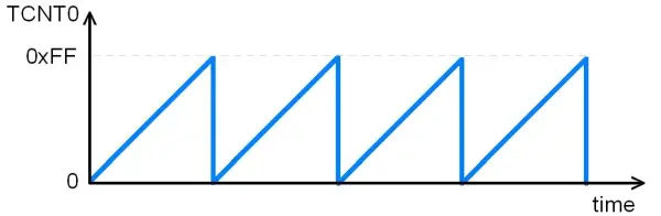
Timer0 Overflow
In normal mode, when the counter overflows, specifically when it goes from 0xFF to 0x00, the TOV0 flag becomes set.
Steps to Program Delay using Timer0
Certainly, here’s a rephrased version:
1. Initialize the TCNT0 register with the initial value, let’s say 0x25.
2. Configure the TCCR0 register for normal mode and choose the clock prescaler option. Once the clock prescaler value is set, the timer/counter commences counting, and with each clock tick, its value increments by 1.
3. Continuously monitor the timer as it counts upwards. Keep an eye on the Timer0 Overflow (TOV0) flag to detect if it becomes set.
4. Halt the timer by setting the TCCR0 to 0, which effectively disconnects the clock source and stops the timer/counter.
5. Clear the TOV0 flag. Note that clearing the flag involves writing a 1 to the TOV0 bit.
6. Return to the main function.
Program for Timer Delay
/*
Generating delay using ATmega16 Timer0
http://www.electronicwings.com
*/
#include <avr/io.h>
void T0delay();
int main(void)
{
DDRB = 0xFF; /* PORTB as output*/
while(1) /* Repeat forever*/
{
PORTB=0x55;
T0delay(); /* Give some delay */
PORTB=0xAA;
T0delay();
}
}
void T0delay()
{
TCNT0 = 0x25; /* Load TCNT0*/
TCCR0 = 0x01; /* Timer0, normal mode, no pre-scalar */
while((TIFR&0x01)==0); /* Wait for TOV0 to roll over */
TCCR0 = 0;
TIFR = 0x1; /* Clear TOV0 flag*/
}
The time delay produced by the code provided can be calculated as follows:
Given that the clock frequency (Fosc) is 8 MHz,
T (time period for one clock cycle) = 1 / Fosc = 0.125 μs
Hence, the counter increments every 0.125 μs.
In the given code, the number of clock cycles required for the counter to roll over can be determined as follows:
0xFF (maximum count) – 0x25 (initial count) = 0xDA, which is equivalent to 218 in decimal.
Additionally, one more cycle is needed for the rollover event and the setting of the TOV0 flag, bringing the total to 219 cycles.
The overall delay is then calculated as follows:
Total Delay = 219 cycles x 0.125 μs/cycle = 27.375 μs.
Example
Let’s rephrase it:
To create a square waveform with a 10 ms high and 10 ms low time, we need to first establish a 10 ms delay using Timer0.
Given that Fosc (the CPU clock frequency) is 8 MHz, and we are using a prescaler of 1024, the timer clock source frequency becomes:
8 MHz / 1024 = 7812.5 Hz
The duration of one timer cycle is:
1 / 7812.5 = 128 μs
Hence, for a 10 ms delay, we need:
10 ms / 128 μs = 78 timer cycles (approximately)
So, to achieve a 10 ms delay, we should set the value of TCNT0 (Timer0’s counter register) accordingly. The value to load into TCNT0 can be calculated as follows:
Value to load in TCNT0 = 256 – 78 (78 clock ticks to overflow the timer)
= 178, which is equivalent to 0xB2 in hexadecimal.
Therefore, by loading 0xB2 into the TCNT0 register, the timer will overflow after 78 cycles, precisely providing a 10 ms delay.
**Note**: All these calculations are based on an 8 MHz CPU frequency. If you are using a different CPU frequency, you should adjust the calculations accordingly to ensure the correct delay duration.
Program for 10ms Delay Using Timer
/*
Generating a delay of 10 ms using ATmega16 Timer0
www.electronicwings.com
*/
#include <avr/io.h>
void T0delay();
int main(void)
{
DDRB = 0xFF; /* PORTB as output */
PORTB=0;
while(1) /* Repeat forever */
{
PORTB= ~ PORTB;
T0delay();
}
}
void T0delay()
{
TCCR0 = (1<<CS02) | (1<<CS00); /* Timer0, normal mode, /1024 prescalar */
TCNT0 = 0xB2; /* Load TCNT0, count for 10ms */
while((TIFR&0x01)==0); /* Wait for TOV0 to roll over */
TCCR0 = 0;
TIFR = 0x1; /* Clear TOV0 flag */
}
Timer Interrupt
![]()
To enable the Timer0 overflow interrupt, we need to configure the TOIE0 (Timer0 Overflow Interrupt Enable) bit within the TIMSK register. This configuration ensures that when Timer0 overflows, the controller will trigger the Timer0 interrupt routine.
Timer0 Interrupt Program
/*
Generating 10 ms delay pulse on PORTB using ATmega16 Timer interrupt
www.electronicwings.com
*/
#include <avr/io.h>
#include <avr/interrupt.h>
/* timer0 overflow interrupt */
ISR(TIMER0_OVF_vect)
{
PORTB=~PORTB; /* Toggle PORTB */
TCNT0 = 0xB2;
}
int main( void )
{
DDRB=0xFF; /* Make port B as output */
sei();
TIMSK=(1<<TOIE0); /* Enable Timer0 overflow interrupts */
TCNT0 = 0xB2; /* Load TCNT0, count for 10ms*/
TCCR0 = (1<<CS02) | (1<<CS00); /* Start timer0 with /1024 prescaler*/
while(1);
}
Video
Source: Timer in AVR ATmega16/ATmega32
- What registers are essential for Timer0 operation?
TCNT0 (timer counter), TCCR0 (timer control), and TIFR (timer interrupt flags) are essential for Timer0 operation. - How do you select Timer0 clock prescaler?
Set the CS02:CS00 bits in TCCR0 to the desired prescaler value according to the CS02 CS01 CS00 table. - How is a delay generated using Timer0 in normal mode?
Load TCNT0 with an initial value, start the timer via TCCR0 prescaler bits, wait for TOV0 flag in TIFR to set, then stop the timer and clear TOV0. - How is a 10 ms delay achieved with Fosc = 8 MHz?
Use prescaler 1024 so timer tick = 128 μs; require 78 ticks; load TCNT0 with 256-78 = 0xB2 to overflow after ~10 ms. - How do you clear the Timer0 overflow flag?
Clear TOV0 by writing a 1 to the TOV0 bit in the TIFR register. - Can Timer0 trigger an interrupt on overflow?
Yes; enable TOIE0 in TIMSK to allow Timer0 overflow to generate an interrupt. - How is PORTB toggled using Timer0 interrupt?
Implement ISR for TIMER0_OVF_vect that toggles PORTB and reloads TCNT0 with the initial value. - What are the Timer0 waveform generation modes?
WGM00 and WGM01 bits select Normal, CTC, PWM phase-correct, and Fast PWM modes.