Introduction
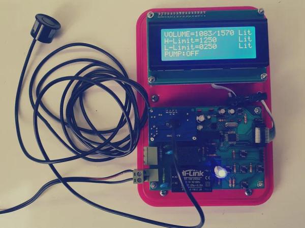
As you probably know, Iran has dry weather, and there is a lack of water in my country. Sometimes, especially in the summer, it can be seen that the government cuts the water. So most of the apartments have a water tank. There is a 1500 litre tank in our apartment which provides water. Also, there are 12 residential units in our apartment. As a result, it can be expected that the tank goes empty very soon. There is a water pump attached to the tank which sends water into the building. Whenever the tank is empty, the pump works without water. This situation causes an increment in motor temperature, and during the time, it can cause pump breakdown. Some time ago, this pump failure happened for the second time for us, and after opening the motor, we saw that coil wires were burnt. After we replaced the pump, to prevent this problem again, I decided to make a water level controller. I planed to make a circuit to cut the pump’s power supply whenever the water came below the low limit in the tank. The pump won’t work until the water rises to a high limit. After passing the high limit, the circuit will connect the power supply again. In the beginning, I searched over the internet to see if I can find a suitable circuit. However, I did not find anything appropriate. There were some Arduino based water indicators, but there could not solve my problem. As a result, I decided to design my water level controller. An all-in-one package with a straightforward graphical user interface to set parameters. Also, I tried to consider EMC standards to be sure that the device works valid in different situations.
Step 1: Principle
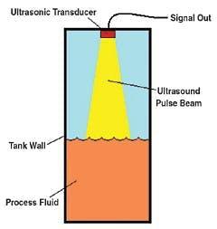
You probably know the principle before. When the ultrasonic pulse signal is emitted towards an object, it is reflected by the object and echo returns to the sender. If you calculate The time travelled by the ultrasonic pulse, you can find the distance of the object. In our case, the item is the water.
Note that when you find the distance to the water, you are calculating the volume of empty space in the tank. To get the volume of water, you have to subtract calculated volume from total tank volume.
Step 2: Sensor, Powersupply and Controller
Hardware
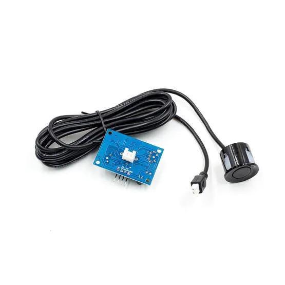
For the sensor, I used JSN-SR04T waterproof ultrasonic sensor. The working routine is like HC-SR04 (echo and trig pin).
Specs:
- Distance: 25cm to 450 cm
- Working voltage: DC 3.0-5.5V
- Working current: <8mA
- Accuracy: ±1cm
- Frequency: 40khz
- Working temperature: -20 ~ 70 ℃
Note that this controller has some limitations. for example :
1- JSN-SR04T cannot measure distance below 25CM, so you have to install the sensor at least 25CM above the surface of the water. Moreover, the maximum distance measurement is 4.5M. So this sensor is not suitable for huge tanks. 2- the accuracy is 1CM for this sensor. As a result, based on the diameter of the tank, the resolution of volume that the device will show can be varied. 3- the speed of sound can be vary based on temperature. As a result, accuracy can be affected by different regions. However, these limitations were not crucial to me, and the accuracy was suitable.
The Controller
I used STM32F030K6T6 ARM Cortex M0 from STMicroelectronics. You can find the specification of this microcontroller here.
The Power Supply
The first part is to convert 220V/50Hz (Iran Electricity) to 12VDC. For this purpose, I used HLK-PM12 buck step down power supply module. This AC/DC converter can convert 90 ~ 264 VAC to 12VDC with 0.25A output current.
As you probably know, the inductive load on relay can cause several problems on the circuit and power supply, and difficulty in the power supply can lead to inconstancy, especially in the microcontroller. The solution is to isolate power supplies. Also, you have to use a snubber circuit on relay contacts. There are several methods to isolate power supplies. For example, you can use a transformer with two outputs. Moreover, there are isolated DC/DC converters out there in a tiny size that can isolate the output from the input. I used MINMAX MA03-12S09 for this purpose. It is a 3W DC/DC converter with isolation.
Step 3: The Supervisor IC
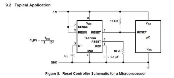
According to TI App note: A voltage supervisor (also known as a reset integrated circuit [IC]) is a type of voltage monitor that monitors a system’s power supply. Voltage supervisors are often used with processors, voltage regulators and sequencers – in general, where voltage or current sensing is required. Supervisors monitor voltage rails to ensure power on, detect faults and communicate with embedded processors to ensure system health. you can find this app note here. Although STM32 Microcontrollers have built-in supervisors such as power on supply monitor, I used an external supervisor chip to ensure everything will work fine. In my case, I used TL7705 from TI. You can see the description from the Texas Instruments website for this IC below: The TL77xxA family of integrated-circuit supply-voltage supervisors is designed specifically for use as reset controllers in microcomputer and microprocessor systems. The supply-voltage supervisor monitors the supply for under-voltage conditions at the SENSE input. During power-up, the RESET output becomes active (low) when VCC attains a value approaching 3.6 V. At this point (assuming that SENSE is above VIT+), the delay timer function activates a time delay, after which outputs RESET and RESET(NOT) go inactive (high and low, respectively). When an under-voltage condition occurs during normal operation, RESET and RESET(NOT) go active.
Step 4: The Printed Circuit Board(PCB)

I designed the PCB in two pieces. The first one is the LCD PCB which is connected to the mainboard with ribbon/flat cable.The second part is the controller PCB. On this PCB, I placed power supply, microcontroller, ultrasonic sensor and related components. And also the power part which is the relay, varistor and snubber circuit. As you probably know, mechanical relays such as a relay that I used in my circuit can break up if they always work. To overcome this problem, I used normally close contact(NC) of the relay. So in a normal situation, the relay is not active and normally close contact can conduct power to pump. Whenever the water come below the Low limit, the relay will turn on, and this will cut the power. Having said that, This is the reason that I used the snubber circuit on NC and COM contacts. Regarding the fact that the pump had high power, I used the second 220 relay for it, and I drive it with the relay on PCB.
You can download PCB files such as Altium PCB files and Gerber files from my GitHub here.
Step 5: Code
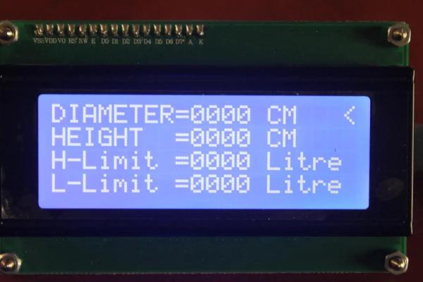
I used the STM32Cube IDE, which is an all-in-one solution for code development from STMicroelectronics. It is based on Eclipse IDE with GCC ARM compiler. Also, it has STM32CubeMX in it. You can find more information here. At first, I wrote a code that included our tank specification(Height and Diameter). However, I decided to change it to GUI for setting parameters based on different specifications.
Source: UltraSonic Liquid Level Controller