The circuit described here demonstrates the working of a radar system. It uses ultrasonic waves to detect an object and measure its distance and angular position, and displays the same on a 20×4 LCD screen. — Ashutosh M. Bhatt is an M. Tech in embedded systems (gold medalist). Currently, he is lecturer in electronics and radio engineering at Government Polytechnic, Jamnagar, Gujarat. He has been working on embedded systems since the last ten years
Radar systems have a number of defence as well as civil applications. Air traffic control uses radars to track aircrafts on the ground and in the air, and to guide planes for smooth landings. Police use radars to detect the speed of passing vehicles. Geologists use radars to map the Earth and other planets. Military uses these for surveillance. Meteorologists use radars to track storms, hurricanes and tornadoes. The list is endless.
A radar system consists of a transmitter that transmits a beam towards the target, which is then reflected by the target as an echo signal. The reflected signal is received by a receiver. This receiver processes the received signal and provides such information as the presence of a target, distance, position (moving or stationary) or speed, which is displayed on a display unit.
Microcontroller based ultrasonic radar circuit
Actual radar systems are built with high-power transmitters and receivers, huge antennae, complex processing systems using digital signal processors and large displays.
This microcontroller based ultrasonic radar circuit demonstrates the working of a radar system. It uses ultrasonic waves to detect an object and measure its distance and angular position, and displays the same on a 20×4 LCD screen. It can detect multiple objects at different angles and distances as new objects are detected. This means that the distance and angle of all objects are displayed one by one on the same LCD screen.
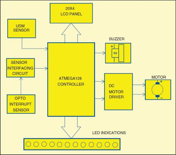
The block diagram of an ultrasonic radar system is shown Fig. 1. The system includes an ultrasonic distance measurment (UDM) sensor, LCD panel, opto interrupt sensor, a motor driver, DC motor, buzzer and LEDs. The schematic of the system is shown in Fig. 2.