Summary of ATMEGA48 TIMER TRIGGERED BY CURRENT FLOW ASM-010
This article describes the ASM-010 project, a timer triggered by current flow using an ATmega48PA microcontroller. It monitors device standby power consumption to calculate working time, storing data in EEPROM upon power failure. The system uses an LM358 or TLC277 operational amplifier for signal processing and drives a 4-digit common anode LED display.
Parts used in theATMEGA48 TIMER TRIGGERED BY CURRENT FLOW ASM-010:
- ATmega48PA microcontroller
- LM358 operational amplifier (or TLC277)
- Quartz resonator (4 MHz)
- Resistor R15
- Transformer
- 4-digit common anode LED display
- EEPROM memory
- Constant voltage power supply (8–30 V)
ATMEGA48 Many devices may be in standby mode during downtime. They do not perform any work, they are apparently disabled, but the control circuits are powered. To extract useful information from the point of…Electronics Projects, ATMEGA48 Timer triggered by current flow ASM-010 “avr project, microcontroller projects, power electronic projects, “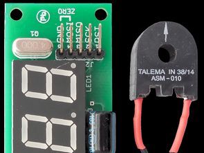
ATMEGA48 Many devices may be in standby mode during downtime. They do not perform any work, they are apparently disabled, but the control circuits are powered. To extract useful information from the point of view of working time, you should download it from the inside of the device, which may end up with a loss of warranty. ATMEGA48
If the sensitivity of the system is too low then the resistance R15 can be increased. Otherwise, if the current in the transformer flows high current, the transformer itself must be adjusted to avoid damage. Used in the prototype ASM-010 is adapted to a maximum of 10 A.
The LM358 is undoubtedly inexpensive, but its disadvantage is its relatively high unbalance voltage, which can, in very unfavorable conditions, mask the sinusoidal input signal. If the changes described above do not work, you may consider using another operating amplifier, eg TLC277. It is important that its input stage properly handles the voltage close to zero.
Once done, the counter system is ready to go. Current consumption is approximately 11 … 15 mA, depending on the current content of the LED display. The power supply should be a constant voltage, well filtered and not necessarily stabilized, in the range of 8 … 30 V.
At the moment of power failure the stabilizer stops supplying the divider and the output of the comparator is set. This rising edge causes the interrupt handler to operate in which the display is turned off, and the current time indication is stored in the EEPROM. This solution does not overwhelm the EEPROM with regular writing, which is justified because the number of write cycles written to it is limited.
ATMEGA48 ASM-010 SCHEMATIC DIAGRAM
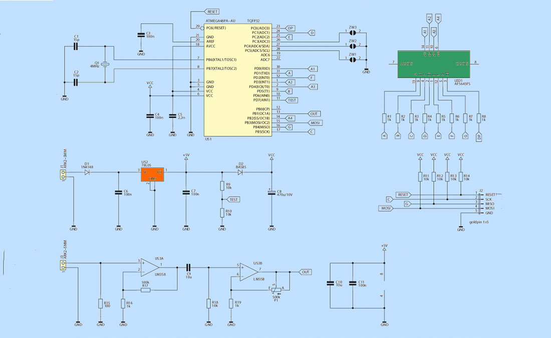
The work time clock schematic diagram The microcontroller used here is ATmega48PA. In this application, its great advantage is the ability to operate at a supply voltage of 1.8 V. This is critical when writing data to non-volatile EEPROM when the system is powered exclusively from the filter capacity. The frequency of the microcontroller clock generator is stabilized with a quartz resonator (4 MHz). The same generator is used to measure time.
The display has 4 digits, each with a common anode. Control of all leads is done directly from the microcontroller terminals because the current of the segments is limited to about 2.5 mA, so that the whole digit does not take more than 20 mA.
Source: ATMEGA48 TIMER TRIGGERED BY CURRENT FLOW ASM-010
- How does the system handle power failure?
The rising edge from the comparator triggers an interrupt handler that turns off the display and stores the current time in the EEPROM. - What is the recommended amplifier if the LM358 fails?
If the LM358 masks the input signal due to unbalance voltage, you should consider using a TLC277 operational amplifier. - Can the sensitivity of the system be adjusted?
Yes, if the sensitivity is too low, the resistance R15 can be increased. - What is the maximum current the prototype handles?
The prototype ASM-010 is adapted to a maximum of 10 A. - What is the frequency of the clock generator?
The frequency of the microcontroller clock generator is stabilized with a quartz resonator at 4 MHz. - Why is the ATmega48PA suitable for this application?
Its ability to operate at a supply voltage of 1.8 V is critical when writing data to non-volatile EEPROM from filter capacity. - What is the typical current consumption of the system?
Current consumption is approximately 11 to 15 mA, depending on the LED display content. - What is the required power supply range?
The power supply should be a constant voltage, well filtered, in the range of 8 to 30 V.