Summary of Using a Quadrature Encoder With an ATtiny 2313 and an OLED Display
This article details a project using an ATtiny2313 microcontroller to interface with a quadrature rotary encoder and an OLED display. The system displays numeric values, a bar graph, and a clock. It covers hardware assembly, setting up the WinAVR development environment, flashing firmware via an AVR Dragon, and explains the logic for detecting encoder direction using state tables.
Parts used in the Rotary Encoder and OLED Display Project:
- ATiny 2313
- 18.432 MHz oscillator
- 7805 voltage regulator
- 10 µF electrolytic capacitor
- 1 µF ceramic capacitor
- 2 x 100 nF ceramic capacitor
- 3 x 10 k resistors
- µOLED-128-G1 display
- Quadrature rotary encoder (e.g., Alps EC12E2420404)
- ATTiny programmer (AVR Dragon)
- Breadboard or veroboard
- Power supply (7 V to 12 V)
- PC with Windows for WinAVR and AVR Studio
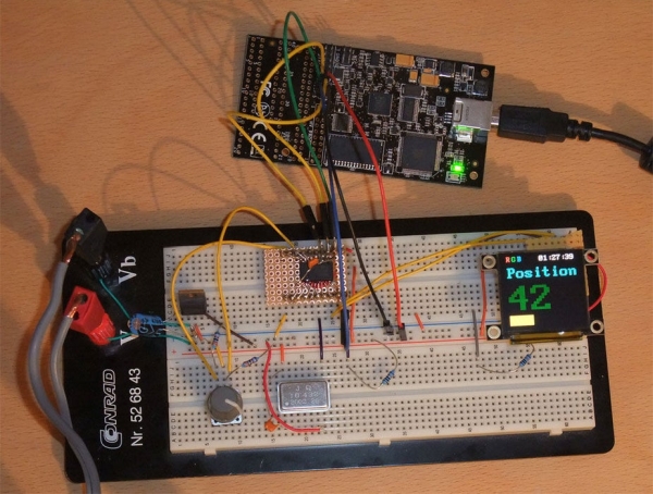
In this instructable you’ll learn how to use a rotary encoder (see http://en.wikipedia.org/wiki/Rotary_encoder ) with a microcontroller and how to display the numeric value as a bar and a numeric value on an OLED display. See the video below for the project in action. The right upper corner of the OLED display shows a small clock, too.
In the image you can see the ATiny2313 in a SMD package, which I’ve soldered on a PCB with headers, but the microcontroller is available in easier to use DIP packages, too.
Step 1: Hardware
You’ll need the following hardware:
* ATiny 2313
* 18.432 MHz oscillator (this frequency is required for a perfect 115,200 baud signal for the OLED display, but the display has auto baud detection, so you can use other oscillators as well, or just the internal oscillator)
* 7805 voltage regulator
* 10 µF electrolytic capacitor
* 1 µF ceramic capacitor
* 2 x 100 nF ceramic capacitor
* 3 x 10 k resistors
* µOLED-128-G1 (from http://www.4dsystems.com.au , but you can use a LCD display, too, or something different, e.g. use the encoder for controlling the pitch of some sound output)
* quadrature rotary encoder (I’ve used Alps, type EC12E2420404, but you can use other encoders)
* ATiny programmer (I’ve used the AVR Dragon: http://www.atmel.com/dyn/products/tools_card.asp?tool_id=3891 )
* a breadboard like you can see in the video, or veroboard and some wires, if you want to solder it
* some tools, like solder iron, if you use a veroboard, side cutter etc.
* power supply (anything from 7 V to 12 V works, even a 9 V battery)
* a PC with Windows for WinAVR and AVR Studio
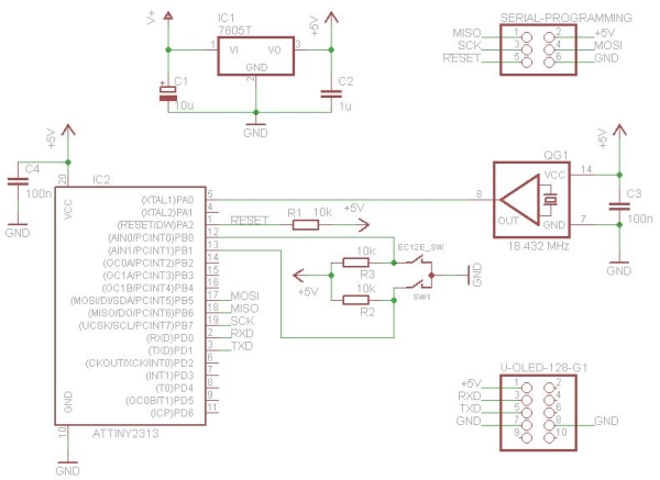
The schematic is very easy to build this on a breadboard:
Step 2: The Development Environment
If you know already how to compile a program for the AVR and how to flash it, you can skipt this step.
I’ve used WinAVR for compiling the project. This is a cross compiler based on GCC, for AVR microcontrollers. It is installed c:\ and I’ve added “C:\WinAVR-20100110\bin” and “C:\WinAVR-20100110\utils\bin” to the system path, for using “make” from the command line.
To flash the microcontroller I’m using the AVR Dragon and AVR Studio 4. After installing AVR Studio 4, install all service packs, connect the AVR Dragon and then execute “Tools->AVR Dragon Upgrade” once, to update the firmware for the Dragon.
For compiling the project, start a DOS command prompt, change to the firmware directory and execute “make”. Flash he resulting attiny.elf file like this: First connect the Dragon with the breadboard, as described in the AVR Dragon manual and on the back of the Dragon. You have to connect all six signals:
MOSI: PB5 of the ATiny 2313
MISO: PB6 of the ATiny 2313
SCK: PB7 of the ATiny 2313
Reset: PA2 of the ATiny 2313
VTG: +5 V power supply of the breadboard
GND: GND of the breadboard
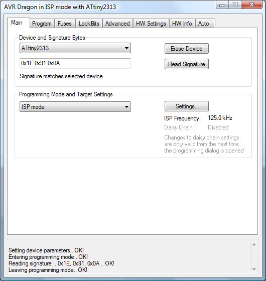
To flash the program to the ATiny 2313, first start AVR Studio and create a new “Assembler” project for the ATtiny2313. Then select “Tools->Program AVR->Connect” and select “AVR Dragon USB”. Select HW Settings Read: now you can see that 5 V is detected, if all connections are right. Select “Main->Settings” and use 125 kHz (less problems with long wires) and confirm with “Write”. Then execute “Main->Read Signature” and you should see the first attached image.
Now select “Main->Erase Device” and select the fuses like you can see in the second attached image. Choose “Program” to program the fuses. Finally select “Program->Flash->Input Hex File:” and choose attiny.hex (it is in the zip file in the next step). If you compile a new version, you need just to erase and flash the new file, which is easy for fast turnaround time.
Step 3: Firmware
Attached is the firmware. You can compile it with “make”, as described in the last step. It is written in a hardware independent way: All functions, which are not standard C, are implemented in hardware.cpp, so porting to another microcontroller is easy. The rotary encoder functions are in main.c. In display.c is are the functions for drawing text, numbers and rectangles. The OLED display has a auto baud detection, so you can use other baud rates as well.
There are two input pins for the rotary encoder to encode the four phases of the quadrature signals (see the Wikipedia image http://upload.wikimedia.org/wikipedia/en/thumb/6/68/Quadrature_Diagram.svg/500px-Quadrature_Diagram.svg.png ). The turn direction can be detected, if you compare the last phase state with the new state, e.g. if it changes from state 2 to state 3 it was turned right and if it changes from state 3 to state 2 it was turned left.
So you need to know the last state and the current state. A state is encoded in two bits. The last state and the next state combined are 4 bits. This is the index in a table with 16 entries, which gives +1, 0 or -1, as the direction in which the rotary encoder was turned.
The table has the advantage that you can easily implement special behaviour, e.g. for the ALPS encoder there are phase transitions at the idle positions, which are ignored, because this resulted in bouncing between two values sometimes. And this halfes the resolution, which results in one counting step per raster.
Bouncing of the contacts is no problem, if the time between comparing two phases is faster than the fastest speed two phases can change.
Source: Using a Quadrature Encoder With an ATtiny 2313 and an OLED Display
- What microcontroller is used in this project?
The project uses an ATtiny2313 microcontroller. - How can I determine the turn direction of the encoder?
Direction is detected by comparing the last phase state with the new state to see if it changes from state 2 to 3 or vice versa. - Does the OLED display support auto baud detection?
Yes, the OLED display has auto baud detection, allowing the use of oscillators other than 18.432 MHz. - What tool is recommended for compiling the firmware?
WinAVR, which is a cross compiler based on GCC for AVR microcontrollers, is used for compiling the project. - Can I use a DIP package instead of SMD for the microcontroller?
Yes, the ATtiny2313 is available in easier to use DIP packages besides the SMD package shown. - How does the code handle contact bouncing in the encoder?
Bouncing is not a problem if the time between comparing two phases is faster than the fastest speed the phases can change. - What specific signals must be connected to the AVR Dragon?
You must connect MOSI, MISO, SCK, Reset, VTG, and GND to the corresponding pins on the ATtiny2313. - Is it possible to port this firmware to another microcontroller?
Yes, the firmware is written in a hardware independent way where non-standard C functions are implemented in hardware.cpp.