Introduction
What is seeing without feeling? The field of Virtual Reality has recently been gaining much attention, with the Oculus Rift and Google Cardboard paving the path of visualizing a world that is not physically there. But what if the virtual reality experience could be enhanced by incorporating tactile sensing? The Haptic Glove we developed accomplishes just that – without seeing the physical structure of the object, you will still be able to feel the presence of virtual objects.
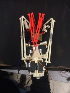
The goal of the project is to create an exoskeleton on the forearm arm that provides tactile perception for the user. The volume of the virtual object will be emulated based on the intensity of a light source that is placed inside a black box. Depending on the relative brightness of the source to the phototransistors that are mounted onto the exoskeleton, a distance between the user’s hand and the light source can be determined. By varying the brightness of the LED light source, the size of the virtual object will vary. To provide the tactile perception, servos mounted on the exoskeleton provides a pulling force, preventing the user’s fingers from reaching closer to the light source. In addition to the resistive force that act against the fingers’ movement, there are also flat surfaces at the tips of the exoskeleton that will flip up to make contact with the user’s fingers, which actually provides the sense of touching a real object.
High Level Design
Rationale and Source of Our Project Idea
Although the technology of haptic feedback has already been developed, it is not a very prominent piece of technology that is being used today. As the market for virtual reality expands and the applications surpass the entertainment realm, we developed our project ‘Virtual Object Grabber’ with the hopes of providing prospective users with an even more immersive virtual reality experience that encompasses the tactile sensory perception.
Background Math
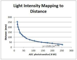
In order to implement a natural interaction with the exoskeleton and the virtual object, we performed a simple mapping of light intensity measured to the distance from the light source. As expected, an exponential decay was observed due to the fact that intensity is inversely proportional to the square of the distance. The exponential decay function was expressed in log and multiplied by scaling factor to obtain a desired linear relationship between light intensity measured and actual distance from the light source.
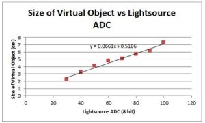
Once the linear relationship between light intensity and distance from the source was established, we created the last mapping of Virtual Object Size to the trimpot ADC measured. The shape of the virtual object was arbitrarily chosen as a sphere due to the 160 degree field-of-view the LED light source provided. With this final linear relationship, we could vary the diameter of the virtual object in centimeters by varying the voltage with the trimpot through the ADC. With all the mappings and relationships developed, we framed the nature of our exoskelton’s interaction with the virtual object.
Logical Structure
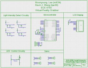
Ultimately, based on a size of an object that the user defines using a potentiometer, the user will experience the sensation of having touched an object when the user’s hand is within the proximity of the virtual object. The following block diagram demonstrates how the entire system works:
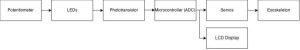
Depending on how large the user wants the object to be, a potentiometier is varied. As the resistance through the potentiometer changes, the brightness of the LEDs will change. The user will be able to see the size of the object that is going to be emulated on the LCD display of the system. Depending on the distance the user’s hand is from the light source, the reading from the phototransistor will vary. This analog value will then be input into the microcontroller via an analog to digital converter (ADC), where the microcontroller will map the analog reading to a distance from the light source. Depening on the location of the user’s hand relative to the light source, the servos that are a part of the exoskeleton will change positions. If the user’s hand is within the distance based on the size of the virtual object that was selected by the user, the servos will pull the user’s fingers back to keep them from moving even closer to the LEDs, or virtual object. In addition to this, on each ring of the exoskeleton that the user’s fingers fit in, there is a flap that will flap upwards to provide the actual sense of touching an object.
Hardware/Software Tradeoffs
Hardware:
When designing the hardware of the system, there were several different tradeoffs that needed be taken into consideration. In the end, the design choices that were made were dependent upon the resources that were available and what we believed would make the most convincing system that provides tactile perception.
Perception VS Size
One major tradeoff that needed to be taken into consideration was the size of the structure that created the exoskeleton versus the perception of feeling a virtual object. When designing the system, we wanted to make the device easily mobile and wearable so that the user is able to use the device in all different sorts of occasions. Since this was the case, we wanted to make the deive as small as possible. However, by reducing the size of the system, the perception of feeling an object that is not physically there was being sacrificed.
One example of sacrificing perception for size is by changing the size of the servos that were used for the exoskeleton. The servos are mounted onto a platform that is strapped to the user’s arm. If the servos are too large, it will make the structure very bulky and heavy, hindering the user’s movement and flexibility. In addition to this, the user’s arm will get very sore after wearing the device for a while, which defeats the purpose of creating a wearable device. On the other hand, if the servos are too small, then there will be a sacrifice in the performance of the system. By using small servos, there will not be enough torque exerted by the servos on the user’s fingers to prevent the fingers’ movement. If the user is still able to move their fingers downwards towards the object when it is not supposed to (as it is within the size of the object that was set), then the entire purpose of feeling a solid object is defeated.
In the end, a medium-sized servo was selected to provide for the movement of the exoskeleton. By selecting the servos that we have, the exoskeleton and mount on the user’s arm are not too bulky and the servos are strong enough to provide the restriction of movement that is required when the user’s fingers are within some distance of the LED light source.
Cost VS Sensitivity
Another tradeoff that needed to be made when designing the hardware of the system was cost VS sensitivity. There is a total budget of $100 that can be spent on completing this project (the total amount spent can be found further down on the web page). With this being a strict limiting factor, we needed to use our resources wisely. With this being said, when purchasing the different components that were a necessary part of the system at large, we did extensive research to see whether the components met the specifications that we needed and to see whether the different components were sensitive enough to provide the perception that we hoped to provide.
Specifically, this tradeoff was most prominent when we were deciding on which phototransistor to purchase. Based on experience of using phototransistors in previous labs, we realized that phototransistors are very directional. By this, we mean that the phototransistor reading is extremely depending on its orientation and on where it is pointing – if it is even the slightest bit angled away from the light source, then the reading of the phototransistor would decay extremely quickly or no reading would be made. With this being the case, we hoped to search for more omnidirectional phototransistors that would be less sensitive to this type of change. Because we decided to operate in the visible light spectrum, there will be a lot of noise due to the ambient light. Thus, we searched long and hard to find a reasonably costed phototransistor that operated within the spectrum that we required and was only sensitive within a certain distance to minimize surrounding noise.
There are definitely higher quality phototransistors out in the market; however, for the budget we have, we were only able to purchase the ones that we did. With the quality of the phototransistors being a design factor, the system was designed around it in attempt to get the correct readings necessary to operate the system.
Software:
There were also several tradeoffs that needed to be made when implementing the software for the system. The decisions that needed to be made ultimately affected the complexity of the system that was created and the user experience most. By making wise decisions in the software implementation, we tried to achieve the best of both worlds.
Complexity VS Time
One software design tradeoff that needed to be made was the complexity of the entire system versus the amount of time that each member of the team has available to complete the project. Each group has a limited amount of time to finish the project before the semester is over; however, there will always be room for improvement, whether it be to implement something in a different way, or to add to the existing system to increase the performance even further. While there is a lot that we hope to accomplish before the project is due, there is only so much that is practical and plausible before we run out of time.
While it may be possible to implement everything that was originally planned, in the end, it comes down to whether the user is convinced that the glove that was created can represent a physical object that is only virtually present in space. With this being the case, writing out the code to achieve this task may be complex and will take a considerable amount of time, but integrating it, debugging it, and modifying it so that the perfomance is convincing is another story.
Specifically, the system could definitely be improved by adding even more sensors to provide not only more accurate readings, but also to allow for different shaped objects and textures. By doing this, the project would be even more interesting and exciting than it already is, but it would boost the complexity of the system by far. With the amount of time to complete the project, however, we found that it would be better to get a stable system working before venturing off to try other things before having a reliably working system.
Processing Power/ Computations VS User Experience
Another software design tradeoff that was needed to be taken into account was processing power versus user experience. When writing software that will be loaded on a microcontroller, it is very important that the user knows how much memory is available so that it is not overwritten, leading to system failures. Additionally, if the program is too large or too much must be computed on the microcontroller, then it will lead to lagging in the system, which would be disastrous in terms of the project that is being completed.
In addition to this, user experience was also affected by the resolution of the readings from the phototransistors and the ADC pin of the microcontroller. If the servos react to every value that is read in, then it is very likely that the servo will twitch because the phototransistor had a poor reading for one cycle or the user moved briefly, blocking the phototransistor from being able to read the correct light intensity. Thus, the values collected can be stored into an array and then averaged before determining the PWM pulse for the servo. By doing so, even though the amount of processing power and the number of computations must increase, the user experience will also increase, as the servo movement will be a lot smoother.
Standards
For our final project, no standards were necessary to be followed.
Copyrights
Doing some research, there are a few companies that develop haptic gloves that are similar to the one that we created for the final project. Specifically, one company is called CyberGlove Systems, which provides different gloves for different applications. While our ideas are very similar, the applications that we and the company aim for are different.
Hardware Design
The hardware that was used in the system consists of both mechanical and electrical components.
Mechanical
All of the mechanical parts that create the exoskeleton were 3D printed in Cornell University’s Rapid Prototyping Lab. First, individual parts were CADed together using SolidWorks and then put together in an assembly file. This file was extracted as a .stl file, which the 3D printing software is able to recognize. Because this resource was readily available to Cornell students to use, several iterations of each part were made before the final version was completed.
Ring
As explained earlier, for the user to experience tactile perception when touching a virtual object, the user’s finger will be pulled backwards and a flap will flip upwards to touch the user’s fingertips. In order to exhibit this sensation, it was decided that the best way to do this was to have the user wear rings that will be connected to servos. Depending on the distance the user’s hand is from the light source, the servos will either pull the user’s fingers back while flipping the flap upwards, or the servos will release the user’s fingers. With this being said, the design of the rings that the user will wear was the most crucial part of the mechanical design for the exoskeleton, as we want the sensation of touch to be as realistic as possible.
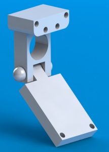
Initially, we thought that the best way to achieve the tactile perception that we hoped for was to make ring that would be pulled back by string that was tied to a servo. The first iteration design of the ring is shown below:

As can be seen from the image above, it can be seen that on top of the ring, there is a structure that contains three holes. Because the initial idea was to have a string pull the flap and finger backwards, the string would go through the top hole and string down into the hole that is in the flap and knotted on the bottom side of the flap. The other two holes on the top structure were for the phototransistor’s leads to fit through. After this first iteration was printed, however, we realized that there were a few design flaws such as the flap not being wide enough and the holes for the string and phototransistor leads not being large enough.
These concerns brought us to create Version 2 of the ring structure. This new version is shown below:
Shown above, the second version of the ring fixed our initial concerns of the flap size not being thick enough and the holes not being large enough. In addition to this, the structure was changed so that rather than having the string go through one hole and knotted at the bottom side of the flap, the string would be strung through one of the holes on the very top of the structure, down through a hole on the flap, and back up around: the string would make a loop that was tied to the servo horn directly. This would not only minimize the amount of interference the string had with the user’s finger, but it also created a more stable system.
After getting this second version of the ring printed and played around with, however, we felt that the exoskeleton was still missing something. The main thing was the fact that we did not like how the string would pull the user’s fingers and the flaps on the ring because it made the structure look flimsy and messy. In addition, if the printed structures only consisted of rings, then it would not be so much of an exoskeleton that we hoped it would be. Thus, the rings were redesigned again to solve our concerns once again, giving us with our final design:
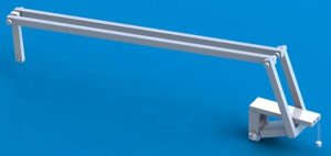
In the final iteration of our design, first of all, it can be seen that we are no longer using string to pull the flap and finger; rather, there are printed rods that will do the pulling. The vertical rod on the very left will connect directly to the servo horn. In addition, it can be seen that the top rod is able to rotate due to the fact that none of its ends are stuck directly to any other part of the ring structure. With this being said, as the servo horn rotates, the flap will either go upwards or downwards. When the flap is pulled far back enough, it will also pull the user’s finger backwards, providing a sensation of the user having touched a solid object.
Another change that has been made in this design is that the top structure of the ring has been extended. Because we did not want the user’s finger or the flap to block the phototransistor from seeing the LED, we made sure that it was able to have a direct line of sight downwards to where the LED structure would be.
Servo Mount
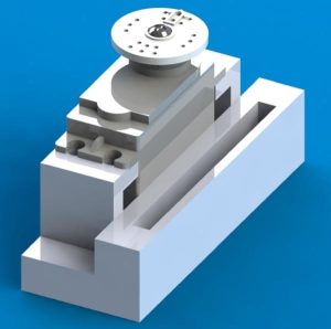
A similar design process was executed for the servo mounts that were created, but this time, only two iterations were necessary. The main design challenge that we had to watch out for was to think about how we were going to mount the servos onto the user’s arm. As stated before, we wanted the entire system to be as mobile as possible. With this being said, it was difficult to think of a structure that would not be too large that restricted the user from moving or from being uncomfortable. In the end, we decided that the best way would be to velcro some sort of mount onto the user’s arm. This would not only allow the user flexibility in movement, but it would also allow the system to be mobile, as it would be easy to put on and take off.
Deciding that the servos should some how be mounted onto the user’s arm using velcro, it can be seen in the final design below that there is a slot for the velcro to be inserted through.
Final Exoskeleton
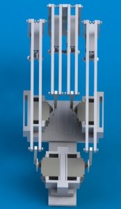
The final step in the mechanical design was to mount everything onto the user’s hand and arm. This also took a couple of design iterations before the final one was decided upon. This task was also challenging because we wanted the mount to be mobile, non-intrusive, and not too bulky.
Initially, when prototyping the final mount for all of the servo mounts, cardboard was used. When doing this prototyping, it was nice because nothing was set in stone, so we were able to test different mounting positions and orientations. After deciding upon the final design, the next challenge was constructing the mount. The main challenge was finding a material that was light enough that the user would not complain about how heavy the mount is while simultaneously being strong enough so that it did not bend. With this being said, the final mount that was strapped around the user’s arm with velcro was made out of one later of aluminum sheet on the bottom with a wooden support on top, which the servo mounts were then attached to. While this structure was strong enough, it was still a little flimsy, so it was reinforced by adding a stainless steel ruler to the very bottom of the mount, under the aluminum sheet, making the structure very rigid and secure. We needed to ensure this rigid structure because we did not want the mount or any of the servos to move when someone is using this system.
Three different views of a CADed version are shown below. The CAD was also made to help visualize how to build the system and to help determine the dimensions of different components that were necessary.
Electrical
The electrical infrastructure of the Virtual Object grabber can be partitioned into four parts: LED light source circuitry, Light detect circuitry, ADC readings, and Servo drive circuitry. The entire schematic of the Virtual Object Grabber is as shown below:
The circuitry for the 1W Ultra Bight LED was initially designed as shown below:
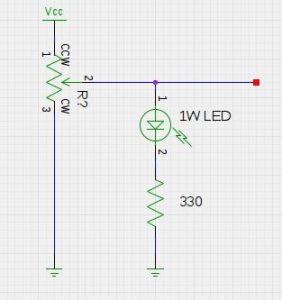
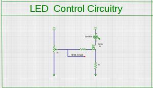
This design, however, demonstrated a severe non-linear light intensity IV curve that was difficult to incorporate in our design. In addition, the brightness of the LED was moderate due to the current limit the potentiometer has to withstand in the current circuit configuration. To obtain a linear IV relationship, the LED circuit was modified as shown below. While the voltage was linear to the NMOS gate, the current was not limited by the potentiometer, which resulted in the optimal behavior we desired. The VCC as shown below were provided by the 9V battery and not from the power supply. When the VCC was initially provided from the same power supply that drove the servos, we observed significant noise due to the servo that would cause the LED to flicker in a noticeable manner.
The light detecting circuitry was soldered and directly placed on the glove of the exoskeleton. The ALS phototransistors utilized for the light intensity detecting on each finger were carefully chosen for its peak sensitivity and operating wavelength at 630 nm. To maximize the omni-direction sensing of the phototransistors, we sanded the cover of the phototransistor so that the light would be refracted in multiple angles to widen its field of view.
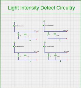
These outputs were inputted into the PORTA ADCs of the microcontroller. The gain of the phototransistors were determined by the resistor value of 5K which provided the most desired behavior in terms of distance mapping. In addition, these signal lines were decoupled with 0.1 uF capacitors to reduce any noise that would be induced by surrounding noise or the long wires from the exoskeleton.
The rest of the schematics for the Virtual Object Grabber can be found in Appendix C.
Software Design
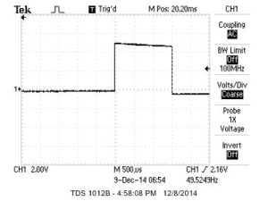
Two Interrupt Service Routines, time2 and timer1, were utilized to implement the Virtual Object Grabber. Timer2 was entered on 1 millisecond intervals in order to decrement the LED and ADC counters for execution. Timer1 was dedicated to incrementing the pwmCount specifically for the servo. In contrast to prior labs in ECE4760, we did not utilize the built-in pwm associated with the timer due to high number of pwm channels needed to drive each servo independently. In order to drive the servos, the pwm period was dictated to 20 milliseconds with each pulse ranging from 1 to 2.5 milliseconds. The width of the pwm was not correlated with the duty cycle but rather the actual period of the pulse that would determine the absolute position of the servo. 1 millisecond corresponded to 0 degrees while 2.5 millisecond pulse corresponded to 180 degrees. Upon implementing the servos on the exoskeleton, however, mechanical constraints and the interface with the resistive force on the fingers proved to be natural only when the angle of the servo was limited to 90 degrees. As such, we scaled the 0-255 8 bit ADC readings to fit the 1.7 to 2.5 millisecond range for the servo pulse in the pwn using the pwmThrehold variables for each pin in PORTB.
The while(1) function in the main loop executed only a limited number of tasks. The first task was the blinkHBEAT() function that would toggle PORTB.0 pin to demonstrate that the board was functioning properly. The next task series of tasks, ad2LCD(), stored the Ain readings from the ADC by switching through the ADC multiplexer and outputting the read values to PuTTY. The most important function in our Virtual Object Grabber was the driveServo() function, where the phototransistor readings from the ADC would be mapped to power decay equation, which would then be converted to units of milliseconds in the variable pwmThreshold. This function essentially utilized the linear relationship between light intensity and distance we developed in the earlier section, and controlled the pwm to provide natural resistive force from the exoskeleton. The pwmThreshold variables had minimum and maximum bounds of 17 and 25, which resulted in 1.7 and 2.5 millisecond of pwm pulse as previously mentioned. The driveServo() function proved to be most difficult and time consuming due to the fact that a linear relationship must first have been established to provide a natural resistive force from the exoskeleton. Much trial and error, in addition to data collection, had to be done before implementing a fine-tuned version of our servo controller function.
In addition, the increments in the timer2 ISR had to be modified accordingly to provide a precise step between each angle for the servos. Bigger increments resulted to ‘twitching’ effects of the servo that would hinder the overall experience of the user.
Although we initially purchased an Inertial Measurement Unit MPU6050 and Flexsensors for further use cases, we were not able to implement those functionalities due to time constraints.
Below is the list of functioned implemented for the Virtual Object Grabber.
void intialize(void);
initialized all port inputs and outputs, as well as setting the timer settings for both ISRs
void intializeIMU(void);
initialize all the parameters required for the MPU6050 IMU.
void blinkHBEAT(void);
toggle the Status LED once a second
void adc_init(void);
initialize the ADC parameters
void driveServo(void);
control the pwmThresholds that would determine the independent angles of each servo
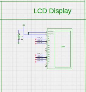
void lcd_init(void);
initialize the LCD display
Results
Speed of Execution
When demonstrating the final project, the speed of execution was not an issue: each servo that controls each individual servo on the exoskeleton acted immediately based on the readings of the respective phototransistor. The only issue that was present with the servos was that they would jitter, especially when the phototransistor was exactly at the distance from the LED source that was set to have an object present. This is because the phototransistor was not able to have a consistent reading due to the noise present in the system and the stability of the user’s hand. Rather than setting one hard threshold value, this threshold could be changed to a range so that the twitching of the servo can be minimized.
Accuracy
During tests and the demo itself, we found that the system was very accurate. One portion of our final project was to have the user grab a virtual object of some size. To determine the accuracy of the system, the user would move his or her hand towards the LED source until the servos pulled back to apply force to the user’s fingers. A ruler was then used to measure the actual disstance between the light souce and the user’s finger, which was compared to the distance that was initially set by the user.
After collecting data by varying the object size and measuring the actual distance between the light source and the user’s finger, it was found that the percent error in distance was roughly 15%. Considering that servos were being used (rather than brushless motors), we believe that this percent error is very tolerable for this system. We thought that this amount of error can be tolerated with servos because the servo horns can only rotate to certain angles which is determined by the pulse width of the PWM signal being sent out by the microcontroller. By switching motors to brushless motors, not only will this percent error be minimized, but the jitter mentioned above will also be minimized – the motion of the motors will be much smoother.
Safety
Initially, safety of the system was one of our main concerns. Using servos, we were not sure whether they would rotate too much that they break the user’s fingers. With this being said, we made sure to buy servos that are limited to 180 degrees of movement. By doing this,the user’s finger may feel uncomfortable when the servo is locked all the way back, but it will not break the user’s finger based on the mechanical design of the exoskeleton.
Besides this, another safety mechanism that was implemented to make sure that the user is not in pain if the servo were to turn the full 180 degrees is that the rod of the exoskeleton is only connected to the servo horn with double sided tape. We realized that this material was strong enough to connect the horn with the exoskeleton, but would also rip apart if too much force was applied to it. Thus, if the finger is being pulled back to an uncomfortable position, the user’s natural reaction would be to act against this motion, thus pulling the rod of the exoskeleton apart from the servo horn.
The final assurance that was made was in software. We made sure that the PWM pulse that was output from the microcontroller does not allow the full 180 degrees of movement. Rather, the servo would only rotate 90 degrees. After doing some testing, we found that 90 degrees was sufficient to have the flap move away from the user’s finger so that they are not touching and to have the flap pull the finger upwards, allowing the user to experience a force acted against the finger.
Usability
As stated earlier, the main reason this project was pursued was that we believe that the field of virtual reality is rapidly improving and becoming a larger and larger part of peoples’ daily lives. We belive that this experience could be enhanced be integrating tactile perception with the visual virtual reality.
There are several use cases for the virtual object grabber that we have created for our final project. The initial idea came from having the possibility of playing piano anytime, anywhere without losing the sensation of playing the full grand piano in a concert hall. With this glove, the tactile perception can be programmed to be similar to the pressing of a piano key. With the further addition of digita synthesis, sound can be integrated with the system and the user will be able to play a piano any time he or she feels.
Another use case for this device would be in the field of medicine, specifically during training for surgeons. Today, surgeons in training use virtual reality to have the visual experience of what will happen when they practice different type of surgeries; however, they are not able to feel what it is like to cut into another human’s flesh or to push a dislocated bone back in place. As the technology of tactile perception develops, it could potentially move into these fields of expertise, providing training for some of the most difficult and stressful careers in the world. By providing trainees with this sense of tactile feedback when training, they will not be in shock when scrubbing in for a surgery, as they have already felt exactly what they will feel during an actual surgery.
Interference with Other Designs
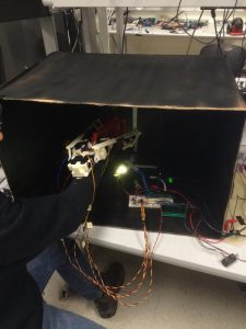
In terms of interference with other people’s designs or the ambient, our system can be affected by any light source. Thus, to prevent this interference, the demonstration was performed in a black box, where the LEDs were placed inside and the user was to reach inside to feel the virtual object.
For other sources of interference, the length of the wire could possibly affect the readings, making them noisier due to the fact that analog data is being sent back a long way from the phototransistors back to the microcontrollers. In addition to creating noisy signals, the long wires could interfere with the user’s mobility, as the wires restrict the movement of the user to a certain distance. To improve upon this, we could use radio frequency to transmit the data instead. However, by using radio frequency, this would lead to other sources of interference that may be more difficult to deal with and even more susceptible to noise.
Moreover, another source of interference of the input signal of the analog to digital converter could be the servos. In our final project, we did not isolate the servos. We did not believe that servos of such small size would affect the readings by too much, but they will still produce noise. With this being said, to further filter out the noise in the system, each of the servos could be isolated from the rest of the system.
Conclusions
The Virtual Object Grabber exceeded our expectations in both the hardware and software aspects. Mechanically, the resistive force and the touching-pads from the exoskeleton compounded to a very realistic experience of touching an actual physical object. Upon reaching the designated distance of the virtual object size, the exoskeleton would provide real-time resistive force that would hinder further approaching to the virtual object. By decreasing voltage across the potentiometer of the light source, the exoskeleton would be able to further approach the light source until reaching the next virtual object size limit. Overall, this projected provided a thorough culminating design experience of noise filtering, real-time processing, mechanical design of the exoskeleton, as well as overall integration of the project as system engineers.
Further improvements for our Virtual Object Grabber would be to control the servos in a more fine scale increments. Due to the fact that the mechanical design of the exoskeleton modified after the framework for the servo control was implemented, each increment in the pwm resulted in a larger step size than desired. This resulted in an undesired outcome of inconsistent and irregular movement of the servo rather than the smooth resistive force desired from the exoskeleton. In addition, more light sources to the overall project would have benefitted us tremendously in that the three Ultra Bright 1W LEDs provided limited field-of-view. With addition of bright or more omni-directional light sources, we will be able to provide a consistent resistive force across all four fingers in the exoskeleton.
Our design did not conform to standards. The only driving factor behind our design was user experience to provide the ultimate virtual reality enhancing tactile system. No intellectual properties were violated during the process of our final project development. Although this project was designed and built by us, we do not claim property to the overall impact and overarching system design for haptic feedback gloves. The ethical consideration for developing the Virtual Object Grabber would be solely confined to the virtual reality realm. Although the design was in form of an exoskeleton, our project application deviates significantly from the conventional exoskeleton uses in military. Because we are currently not intending to further pursue this project through patenting in any way, there are no legal considerations to be addressed.
Appendices
A. Commented Program Listing
B. Graph Results: Oscilloscope Screen Shots
C. Other Schematics
Source: Virtual Object Grabber