The main aim of this project is to come up with a functional WiFi switch that will help us operate via the “Blynk” app from the Mobile app store.
This Instructable is successfully tested with very basic knowledge of Electronics and I would appreciate suggestions from professionals in the domain to comment for appropriate changes.
Supplies:
The following components are required to successfully complete the project
- NodeMCU
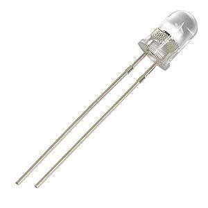
- White LEDs – 10 Nos
- Multimeter
- Soldering Iron
- Soldering Lead
- Soldering Flux
Step 1: WiFi LED Switch Using NodeMCU & Blynk
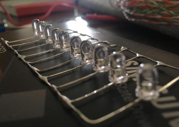
The very first step is to check and lineup LEDs in accordance with their polarity (Anode & Cathode lined up for easy identification)
There may be a few LEDs that may nor be functional, hence it is always suggested to check each one of the LEDs using Multimeter.
Step 2: Identifying & Soldering Working LEDs
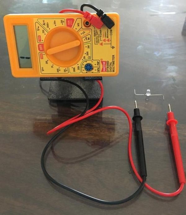
Continuity check using Multimeter will help us identify the functional LEDs and the faulty ones.
It is always better to tape the LEDs WRT their polarity and make them ready to be soldered.
On completion of soldering all 10 LEDs, it is once again suggested to check the continuity using a multimeter.
LED is functional only if the positive lead of the multimeter when connected to the Anode and the negative lead of the multimer to the Cathode helps the LED mildly glow.
On completion of soldering all LEDs, we can primarily check if all the LEDs are glowing with help of a 9V Battery (Connections to be made keeping Polarity in mind)
Note: If there is a failure LED, you may see something similar to one of the images uploaded where the Multimeter displays a value of 1607.
Step 3: Connecting NodeMCU & Uploading the Code Via Arduino IDE.
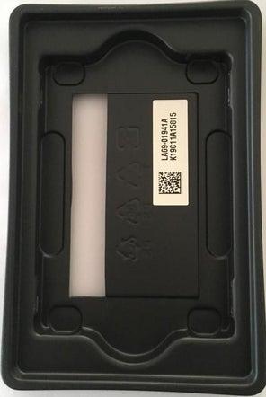
Packaging the prototype is important and I found a “Solid State Drive (SSD)” packaging tray to be most appropriate to package the soldered LEDs and NodeMCU.
The connections are very simple and are as follows:
1. Connect “D1” pin of NodeMCU to the Anode of soldered LEDs and
2. Connect the “GND” pin of NodeMCU to the Cathode of soldered LEDs.
Note: Please refer to the attached screenshot for the complete code. It seems some portion of code is missing, especially with the “include” statements while placing the subsequent text in between less than and greater than symbols.
Upload the following code to NodeMCU:
#define BLYNK_PRINT Serial
#include ESP8266WiFi.h
#include BlynkSimpleEsp8266.h
char auth[] = “**************************************************”;
// Your WiFi credentials.
// Set password to “” for open networks.
char ssid[] = “************”;
char pass[] = “*****************************”;
void setup()
{
// Debug console
Serial.begin(9600);
Blynk.begin(auth, ssid, pass);
// You can also specify server:
// Blynk.begin(auth, ssid, pass, “blynk-cloud.com”, 80);
// Blynk.begin(auth, ssid, pass, IPAddress(192,168,1,100), 8080);
}
void loop()
{
Blynk.run();
}
Step 4: Blynk – Configuration & Testing.
Finally, it is time to configure and test the prototype functionality using the mobile application “Blynk”.
Please take the necessary help from the attached screenshots to complete and run the prototype successfully.
The following step by step instructions will help the reader of this article:
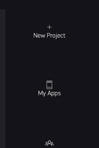
- Install and open the Blynk App on mobile.
- Give the project a name: “WiFi LED Switch IoT” in this case. You may choose your own terminology to name it.
- From the drop-down list, choose the device using which the experiment is completed.
- On selecting “Create”, an “Authorization Token” is shared with the registered/configured Email ID.
- It is now time to add components to the project. We will need only one “Button” in this case.
- Furthermore, the button “Output” setting needs to be changed to indicate the Digital pin on which the LED in series is connected (D1 in this case).
- Continue to configure mode to “Switch” to complete the configuration.
- Choose a convenient location for the “Button” to be placed on the dashboard and select the “Play” button at the top right corner of the interface to start interacting with the board.
- You should now be able to control your LEDs in series from anywhere & any time.
In case of any further help, you may WhatsApp me on +91 9398472594.
Source: WiFi LED Switch IoT