Introduction
There’s a simple question asked by runners, walkers, joggers, and anyone who moves. How fast am I going? Runners want to pace themselves, athletes are trying to train for events, and even on a day to day basis you might wonder how far you are travelling. There are various existing methods of measuring pace, including step counters, GPS units, and smartphone applications. Pedometers are a common method of tracking physical activity. However, many pedometers are self-contained units that are often out of sight and out of mind. Our wireless pedometer not only records steps, but sends this information wirelessly to a wrist-mounted module. This wrist unit provides users with easily accessible information about the number of steps they’ve taken, their pace, and the timing of their steps. The tracker also calculates and displays the speed at which the user if moving, given an average stride of the user.
igh Level Design
Rationale and Source of Our Project Idea
Our team has an interest in running and walking, and we have noticed that existing systems make it difficult to actively monitor your number of steps as well as your pace. Applications on your phone may only work in environments with cell phone coverage, and may not be practical for longer runs that require extended battery life. Pedometers placed on the waist are difficult to check quickly. There are some pedometers, like the Nike FuelBand, which are placed on the wrist, but these suffer in accuracy due to their placement. Our idea was to take the best of both worlds: create an easily read, low cost pedometer that displays its information on the wrist while still accurately measuring the number of steps with a detector placed near the foot.
Background Math
The mathematical grounding of our project are Newton’s equations of motion as well as the acceleration equations.
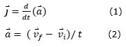
Using Equation 1, we know that taking the derivative of acceleration with respect to time results in the jerk of the system. By looking at the zero crossing of jerk from a positive to a negative value, we recover the peak acceleration of the accelerometer. This peak in acceleration corresponds to a foot hitting the ground or a foot rising very quickly from the ground. However, depending on our threshold, we may not be able to catch all steps if we have the accelerometer on one ankle. This is because the acceleration on a step up is oftentimes less than the acceleration on a step down. An example of this behavior is included in the section Software Design: Step Detection Algorithm. Because of this, it is also helpful to consider the jerk, as upward foot movements still have a unique jerk signature. We can look for these upward foot movements by scanning for data with high absolute jerk, and then processing them with a lower peak acceleration threshold. By finding appropriate peaks in acceleration on a single foot, we can accurately measure the number of steps that a person has taken using one single-axis accelerometer. More information about existing footstep detection algorithms can be found in the References Section.
Using equation 2, we can extract the user’s velocity directly from an accelerometer orientated parallel to the direction of motion. The initial velocity and initial time are set by the detection of a footstep using the jerk scheme described above. Until the next footstep, the acceleration readings are summed. Then, upon detection of the next footstep, that accumulated acceleration is divided by the change in time, resulting in the final velocity in the direction of motion. We were able to implement this functionality in our system. However, our accuracy was extremely low because we were using a one-axis accelerometer. In order to get decent accuracy, the accelerometer would have had to been perfectly aligned and oriented. Had we used a three axis accelerometer, we would have been able to recover the user’s velocity, among other benefits. This extension will be discussed further in the Conclusions section. Our current system discards this x-axis information, and uses the user configured step length to give an accurate estimate of the user’s pace.
Logical Structure
At a high level, our system has two main logical and physical units:
- Foot Module
- Wrist Module
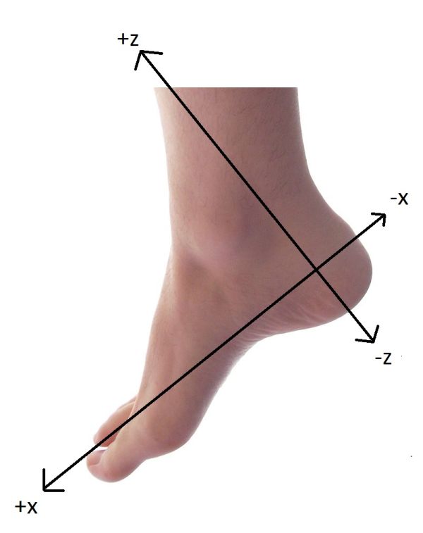
The foot module uses an accelerometer to measure the acceleration and deceleration of the foot in the z-axis. It does light processing of the data, then packages this information and sends it over Bluetooth to the wrist module. The wrist module uses information received from the foot to calculate whether a step has occurred. It then displays this information to the user on an LCD screen. The wrist module also takes inputs from the user to set the desired pace and stride length. Both modules contain an ATMega1284P microcontroller running on the Tiny Real Time (TRT) Kernel and an HC-05 Bluetooth master/slave transceiver.
The user interfaces with the device using the wrist module. The wrist module powers up in a configuration mode. In this mode the user can use the two push buttons to adjust his or her stride length and also the desired speed. An enter button allows the user to enter into pace display mode. At any point the user can re-enter configuration mode by toggling a switch on the wrist module. In configuration mode, the wrist module is still capable of collecting and processing data. It is only the information that’s displayed on the LCD that has changed.
Hardware and Software Tradeoffs
There are several important software and hardware tradeoffs in our system. When dealing with the accelerometers, there were a few occasions when we had to decide between implementing a feature in hardware or in software. The accelerometers have the option of a self-test to recover from hardware errors and verify that the chips are functional. The self test results are output on pin 4 of the accelerometer. Should this result be high, as it is upon power-up, the accelerometer is compromised and the self-test must be run. This self-test involves setting and resetting a pin on the chip. We could have done this with software in our initialization code, or set-up an interrupt handler to reset the accelerometer when needed, but we chose to implement it in hardware using LEDs and switches. This is because various hardware events cause the accelerometers to malfunction and require a reset – power cycling, wire shorts, popping out of the breadboard, and many other malfunctions more probable in prototypes than a polished product. A hardware reset alerts us to a possible hardware malfunction so that we can address it, rather than continuing to receive potentially faulty data.
We also chose to use accelerometers that output an analog value rather than a pre-converted digital value. The reasons for this include: cost, ease of use, and transparency in functionality. First off, accelerometers that output an analog value corresponding to acceleration are cheaper and more widely available from vendors. Furthermore, as we were going through the implementation process, it is much easier to hook up an oscilloscope to an accelerometer outputting an analog value. Had we used a digital accelerometer, we would need to use pulse width modulation in the MCU or some similar scheme in order to visualize the changes in acceleration during human motion. Also, when connecting the accelerometer to the board, we can simply attach the output to an internal A/D converter in the MCU. A digital accelerometer would need to communicate over some serial communication protocol – SPI, I2C, or UART – to name a few. Finally, by using an analog accelerometer, our MCU get’s to control exactly how many digital samples it receives and at what accuracy. We are the ones who actually get to control how we take in data.
Lastly, we chose to use 1.5g accelerometers simply because they were the most appropriate range of parts that were free for us to use, and because we did not have the time in our schedule to sample some parts we were interested in. The class of accelerometers we ended up using are only available as 1-axis components.
There was a major tradeoff within the software as well. To maximize the number of readings that we get from the accelerometer, the foot would ideally only be running the A/D conversion. However, this raw acceleration information must be processed to calculate jerk and detect a step. To do this, we chose to send the information over Bluetooth to the wrist module. The wrist module does not have that same A/D computation constraint. It can take its time doing the long jerk calculations and determining when a step has occurred, leaving the foot module to focus on just grabbing the analog acceleration data, converting it, and sending it over Bluetooth.
The foot module, in order to both read and write the measured A/D value, must protect this variable with semaphores. Because of this constraint, we chose to run the multitasking TRT kernel on the foot module. Although some cycle time is lost in order to run TRT, this is offset by the ability to execute atomic reads and writes of a shared variable. The wrist module also has several tasks that it must run at once with shared variables among those tasks. For this reason, we run TRT on the wrist module as well.
Finally, there is a software tradeoff in choosing when to send the acceleration information from the foot to the wrist. If we sent all of the information from the z-axis and x-axis accelerometers, the wrist starts to spend more and more time in the task that receives the data, leaving little room for other important tasks like calculating jerk and updating the LCD. Furthermore, as the load increases on the Bluetooth channel, the latency increases as well, and at a certain point, packets are dropped. To mitigate this slowdown we do some preprocessing on the foot module to determine what data actually should be sent. We carefully balance doing pre computations on the foot that reduce the wrist’s amount of receive work with the need to avoid excessive computation on the foot that prevents the A/D conversion from running as much as possible. The details of this are described further in the software design portion.
Standards
The Bluetooth HC-05 boards that we purchased follow the Bluetooth standard as set by the Bluetooth Special Interest Group (SIG) and connect to the MCU via UART. There is no packet structure standard to follow, so we implemented our own. The Bluetooth protocol is described in detail in Appendix D: Bluetooth and HC-05 Bluetooth Configuration and Usage.
While testing our modules we used the RS232 protocol via a MAX232 converter to probe Bluetooth communication on the PC. However, we removed all traces of the RS232 probe from our final board to reduce our hardware footprint and to make the unit fully wireless and mobile.
Relevant Copyrights
Both of the MCU’s that we use in our project are running the Tiny Real Time kernel developed by Dan Henriksson and Anton Cervin at Lund University. TRT was originally a kernel developed for the Atmel AVR Mega8 microcontroller. The version we use has been modified by Bruce Land, ECE 4760 instructor, to run on the Atmel AVR Mega1284.
We use a modified LCD library and header from scienceprog.com to initialize and communicate with the LCD screen. Modifications were made and documented by ECE 4760.
To help develop the step algorithms of our project we looked at an ECE 4760 final project: “Intelligent Wireless Pedometer” by Andrew Chin and Ping-Hong Lu. This project was reviewed for its information about how to find speed from acceleration information, a feature that we ended up not including in our final product. We also looked at the ECE 4760 project “A Wireless Programmable Pace Clock” by Paul Swirhun and Shao-Yu Liang for their implementation of a Bluetooth module. However, in our project we chose to use a much different, much cheaper Bluetooth module than this project. Finally, we looked at various A/D converter code examples on the ECE 4760 website to implement A/D conversion. Further discussion of relevant existing patents, copyrights, and trademarks is included in the Conclusions Section.
Hardware
Hardware Overview
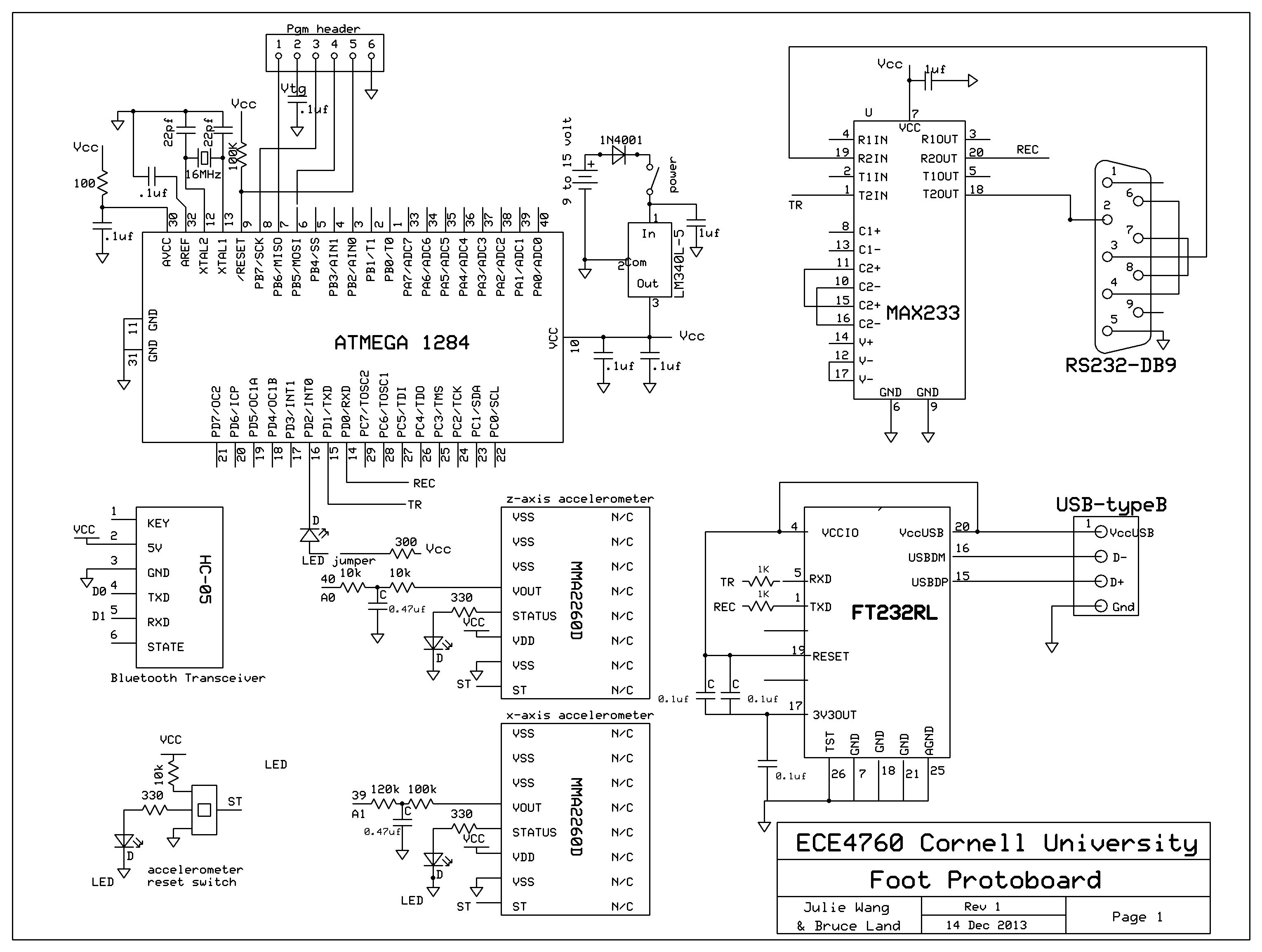
As mentioned in the high level overview, our project consists of two main hardware units: a foot module and a wrist module. The electrical schematics for our design are included in Appendix A: Schematics. A table of all ports used on both microcontrollers is included below. We will now examine the hardware on each module in detail.
Parts List
| Part | Vendor | Cost/Unit | Quantity | Total Cost |
|---|---|---|---|---|
| Atmega 1284 | Lab Stock | $5.00 | 2 | $10.00 |
| MMA2260D X-Axis 1.5G Accelerometer | Freescale Semiconductor/Lab Stock | $0.00 | 2 | $0.00 |
| 2-pack HC-05 Bluetooth Modules | NY Platform (eBay) | $16.58 | 1 | $16.58 |
| White board | Lab Stock | $6.00 | 1 | $6.00 |
| Solder Board (6″) | Lab Stock | $2.50 | 1 | $2.50 |
| LCD (16×2) | Lab Stock | $8.00 | 1 | $8.00 |
| SOIC Carrier Board/Breakout Board | Lab Stock | $1.00 | 2 | $2.00 |
| 9 Volt Battery | Generic | $2.00 | 2 | $4.00 |
| Two Pin Flat Jumper Cables | Lab Stock | $1.00 | 2 | $2.00 |
| Duct Tape | Lab Stock | $0.00 | 1 | $0.00 |
| Potentiometer | Lab Stock | $0.00 | 1 | $0.00 |
| Wires,Resistors,Capacitors | Lab Stock | $0.00 | several | $0.00 |
| Buttons, Switches, LED’s | Lab Stock | $0.00 | several | $0.00 |
| TOTAL: | $51.08 |
For more detail: Wireless Pedometer Using Atmega1284