This webpage describes the development of a Stabilized Gimbal Control System for the CUAir team, Cornell University’s Unmanned Air Systems Team. The Stabilized Gimbal Control System will help the CUAir team compete at the Association for Unmanned Vehicle System International (AUVSI) Student Unmanned Air Systems (SUAS) Competition. The system developed will help the team accomplish the off-axis target imaging task, accomplish the egg-drop task, and improve the task of imaging targets below the aircraft.
This project consisted of the design and construction of a Gimbal Control Board, and the development of the software that executes both on the micro-controller and on the aircraft’s payload computer. This project did not consist of building the physical gimbal that the Gimbal Control Board will actuate. The Gimbal Control Board contains an onboard 6-Axis Inertial Measurement Unit (IMU), headers for a GPS module, 5 servo connections with optical isolation, voltage regulation, and an Atmega128 micro-controller. The software developed provides a high performance asynchronous serial communication library, software to read and parse data from the GPS and IMU, software to control the servo signal lines that command the servo to actuate to certain angles, software to stabilize the gimbal system’s pointing angle, and software to point the gimbal at a specified GPS position.
This webpage contains the high level details for the design, development, and evaluation of the Stabilized Gimbal System. A more detailed report of the design and development can be downloaded here.
High Level Design
This section describes the high level design of the Stabilized Gimbal System. This includes the motivation for the project, the background math, the hardware and software tradeoffs, existing designs, and relevant standards and regulations.
Project Motivation
This section describes the motivation for the Stabilized Gimbal System Project. The first subsection describes the Association for Unmanned Vehicle System International (AUVSI) Student Unmanned Air Systems (SUAS) Competition. The second subsection describes the CUAir Project Team, an engineering team at Cornell University that competes in the AUVSI SUAS Competition. The Stabilized Gimbal System described in this document was developed for the CUAir team. The final subsection describes the motivation for the Stabilized Gimbal System, and how it relates to the AUVSI SUAS Competition and the CUAir team.
Association for Unmanned Vehicle Systems International (AUVSI)
Student Unmanned Air Systems (SUAS) Competition
The AUVSI SUAS Competition is an annual competition in June that takes place at the Webster Field Annex of the Patuxent River Naval Base. The competition focuses on building unmanned air systems that can complete reconnaissance missions with real-world constraints. College teams from around the world attend this competition. Last year over 40 teams registered to compete, about 35 teams attended the competition, and about 32 teams flew their aircraft at competition.
Competition Components. The competition is broken into three components: the technical journal paper, the flight readiness review presentation, and the simulated mission. The components are worth 25%, 25%, and 50% respectively. The journal paper is a 20 page paper that focuses on the design and testing of the air system. The flight readiness review presentation focuses on why the team is confident the air system will perform a safe and successful mission. The simulated mission is a sample mission where students are given mission parameters and expected to perform the mission within the given time-frame and mission parameters.
The Simulated Mission. The simulated mission is broken into eight sections: mission setup, takeoff, waypoint navigation, search grid, emergent target, Simulated Remote Intelligence Center (SRIC), landing, and cleanup. Mission setup involves transporting the competition gear to a designated site within 5 minutes, unpacking and settings up the gear within 15 minutes, and then beginning the mission. Teams are not allowed to turn on aircraft components or wireless gear during this setup phase. After the 15 minutes of setup the mission starts, which means students have 30 minutes to complete all simulated mission components. The first component is autonomous takeoff, which is usually attempted once ground checks have been completed. The second component is waypoint navigation, where the aircraft must follow a specified flight path within a certain tolerance. The third component is the search grid, which is an area of abnormal shape which may contain targets of interest. The air system must stay within the search grid at all times, and must enter and leave the grid at a specified location. The judges will at some point indicate the location of an emergent target, which is a target of interest with an approximate location. Teams are required to dynamically re-route to this location. The teams then attempt the SRIC task, which involves downloading information from a remote WIFI network and relaying this information back to the ground system. Finally, the air system lands and data is given to the judges. The air system is tasked with identifying and classifying targets of interests that are located within the mission area during the course of aforementioned flight operations. Teams are judged based on targeting performance and level of system autonomy. Once the mission is complete, teams have 15 minutes to cleanup the area and leave the mission site.
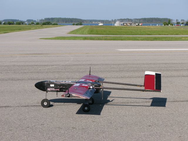
Ground Focused Imaging. A core focus of the competition is the ability for the air system to take pictures of the ground and identify targets of interest. The air systems must achieve good imagery ground coverage as the target identities and locations are not known to the teams beforehand. Most teams bring fixed-wing aircraft to the competition due to their better performance in long range flight, stabilized flight in wind, and flight with heavy payload components. These aircraft change attitude by actuating flight surfaces to roll or pitch the aircraft. When the aircraft changes attitude, the payload also changes attitude. This means that cameras that point at the ground to take images are no longer pointed at the ground when the aircraft changes attitude from a level position. The aircraft changes attitude during turns, and in response to wind that moves the aircraft off desired flight-path. This means that during these events the air system does not take pictures of the ground, which could cause the system to miss targets entirely and hurt mission performance. A stabilized gimbal system can actuate the camera in response to these attitude changes to keep the camera focused on the ground where targets are located.
Off-Axis Target Imaging. During the waypoint navigation phase of the simulated mission the air system is required to image a target with known location that does not appear directly below the air system’s flight path. That is, a camera system which only points directly down cannot image this off-axis target. There are two ways to solve this problem: use multiple cameras that are fixed so as to cover any off-axis target, roll the aircraft to align the camera with the target, or use a stabilized gimbal system that can point at the known GPS location as the aircraft is passing the target. Multiple cameras are usually prohibitive due to size, weight, and cost. Rolling the aircraft will cause it to deviate from the required flight-path and may cause the aircraft to exceed the path tolerance. Thus, a stabilized gimbal system is best for a fixed-wing aircraft to image this required off-axis target.
New Competition Components. The 2014 AUVSI SUAS Competition have a few new components than previous years. The two major components are infrared imaging and egg drop. The infrared imaging task is to identify a target of interest that requires an infrared camera to be seen. Infrared cameras are significantly more expensive at higher resolutions, which will require teams to purchase lower cost cameras that have the ability to zoom. Cameras that zoom require a gimbal system to be effective as the probability of a target appearing perfectly below the flight path is very small. The egg drop task is to drop a plastic egg with flour inside to hit a known target. There are many ways to accomplish this task, but most require the actuation and positioning components that are inherent to a stabilized gimbal system.
CUAir: Cornell University Unmanned Air Systems Team
CUAir is Cornell University’s Unmanned Air Systems Engineering Project Team. The team consists of about 40 undergraduate students, up to 1 graduate student, and a faculty advisor. The faculty advisor for the team is Professor Thomas Avedisian of Cornell University’s MAE School. The team is structured into five subteams: airframe, autopilot, software, electrical, and business. There is a team lead that manages the entire team, and five subteam leads that manage their respective subteam. Phillip Tischler is a member of the CUAir team. From 2012-2013 he was the full team lead, from 2011-2012 he was the software subteam lead, and 2010-2011 was his first year on the team. Phillip Tischler is the single graduate student for the 2013-2014 year.
Team History and Goals. CUAir, Cornell University Unmanned Air Systems, is an interdisciplinary project team working to design, build, and test an autonomous unmanned aircraft system capable of autonomous takeoff and landing, waypoint navigation, and reconnaissance. Some of the team’s research topics include airframe design and manufacture, propulsion systems, wireless communication, image processing, target recognition, and autopilot control systems. The team aims to provide students from all majors at Cornell with an opportunity to learn about unmanned air systems in a hands-on setting. The team was founded in 2002. In 2012 the team placed 2nd Overall, and 1st in Mission Performance. In 2013 the team placed 1st Overall, 1st in Mission Performance, and 1st in Technical Journal Paper. The team hopes to continue this success in the 2014 competition.
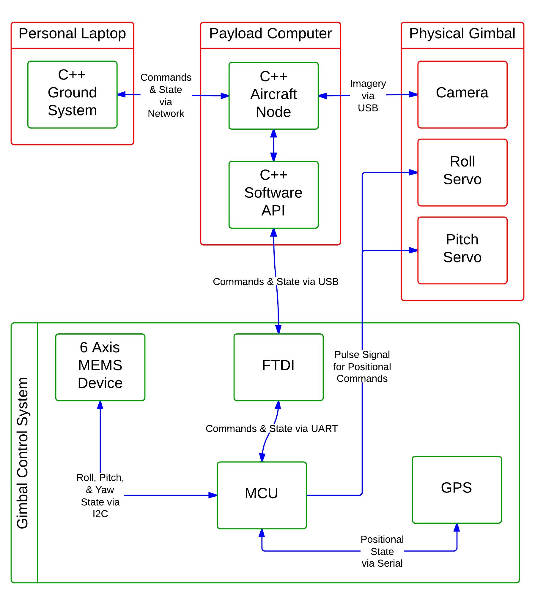
Overall System Design. The image below shows the design of CUAir’s full system. It is quite complicated and out of scope for this document. From this figure you can see that there is a message passing layer that can carry data and command messages from various nodes in the system. The aircraft node is the software process located on the aircraft’s payload computer that controls all payload components. This software node can communicate with any onboard gimbal control systems and be a middle-man for any data or command messages that come from the ground system. Any gimbal control system simply needs to be integrated into the aircraft node, and then the gimbal is fully integrated into the rest of the system.
CUAir’s Overall System Design. The top portion of the diagram shows system components that are located in the aircraft. The bottom portion of the diagram shows system components that are located in the ground station. As shown, the gimbal control system is controlled by the payload computer which executes the aircraft node software process.
Stabilized Gimbal System
A Stabilized Gimbal System would greatly improve the mission performance of CUAir’s air system at the AUVSI SUAS Competition. Such a system would increase the amount of imagery ground coverage by focusing the camera system on the ground during attitude corrections that roll and pitch the aircraft. Such a system would also allow the air system to image off-axis targets reliably. Commercial systems are not a viable option for the CUAir team. The commercial systems the team investigated indicated that such systems were either lacked performance, were prohibitively expensive, or did not allow the required system integration the team would need. As such, the team decided it is best to build a custom Stabilized Gimbal System.
CUAir previously attempted to build a Stabilized Gimbal System, but that effort was mostly unsuccessful. However, the lessons learned during that effort guided this new system to success. Previously, the mechanical system relied on gears that allowed the gimbal to move in between commanded set points. This greatly decreased the accuracy and reliability of the camera actuation. The new gimbal system developed uses mechanical arms that remove this “slop” in the gimbal mechanism. Second, the gimbal suffered from twitching servos due to a noisy power supply as well as signal corruption. Signal corruption was caused when the servos produced back-emf on the same line as the pulse signal controlling the servo’s position. The new gimbal system uses linear voltage regulators to smooth the power supply, and optical isolation chips to prevent signal corruption. Third, the accelerometer and gyroscope chips used to calculate the gimbal’s state suffered from axis misalignment and mis-calibration. The new gimbal system has a single chip with internal axis alignment, factory-calibrated axis alignment, and internal calibration. Finally, the communication interface was previously selected to be Ethernet, a choice which drastically complicated the project and caused the gimbal control boards to take up much more space. The new gimbal system uses regular serial communication with a USB connection.
This project will provide CUAir with a gimbal system that can actuate a camera accurately and reliably, communicate with a host computer to convey state information and receive command settings, to calculate its state from on-board sensors, to stabilize the camera system so as to keep it pointed at the ground, and finally to point the camera system at a known GPS location. Such a system will help CUAir excel at the 2014 AUVSI SUAS Competition.
Background Math
This section explains the prerequisite math necessary to understand the rest of the design and development. The two largest components explained in this section are Q Number Format and Quaternions.
Q Number Format
Micro-controllers do not have floating point hardware. Floating point math is simulated by the micro-controller using integer math. The result is that floating point operations take 100 to 300 cycles to complete. Many floating point operations can slow down the micro-controller drastically. The Stabilized Gimbal System needs to perform many calculations, must store various forms of data, and must be able to serialize that data. Q Notation math can provide 2 to 4 times speedup compared to floating point math. It also makes serialization the task of serializing an integer, not a floating point number.
Consider the math required to convert a quaternion to euler angles. There are 15 multiplications, 4 additions, 3 subtractions, and 3 trigonometry calculations. Lets assume that each arithmetic operation takes 200 cycles and each trigonometry calculation uses about 1000 cycles. This means each calculation requires 22*200 + 3 * 1000 = 7400 cycles needed per calculation. This calculation is done at 200Hz, which means it takes up about 1.48MHz of the processor. In reality the calculation will not be perfectly efficient and more cycles will be used that this lower bound. Approximately 1/8 of the micro-controller’s CPU will get used to simply convert the representation of rotation. Q number format can cause the same calculation to only take 1/32 of the CPU.
Q Number format represents a decimal number as an integer number and a fractional numerator. The Q number is usually expressed as Qm.n where m is the number of bits used for the integer number and n is the number of bits used for the fractional numerator. The integer number occupies the highest m bits of the number and the fractional numerator occupies the lower n bits of the number. Lets say the value of the m bits is a and the value of the n bits is b, then the value of the number is a + (b/(2^n)) and the number is represented in memory as ((a << n) | b). Converting a floating point number to Q number format means multiplying by the number by 2^n and rounding the value to the nearest integer. Converting from Q number format to floating point means converting the integer value to a floating point value and multiplying by 2^-n. The value of n is chosen prior to execution, so the values of 2^n and 2^-n can be computed and stored prior to execution.
The numbers are represented as fractions, so additions and subtractions are equivalent in the Q number format. For multiplications and divisions, the answer must be multiplied or divided by the denominator respectively. This can be accomplished by left shifting or right shifting respectively.
For more detail: Stabilized Gimbal System Using Atmega1284