Introduction
The following diagram shows the system schematic of the Smart Plant Feeder.
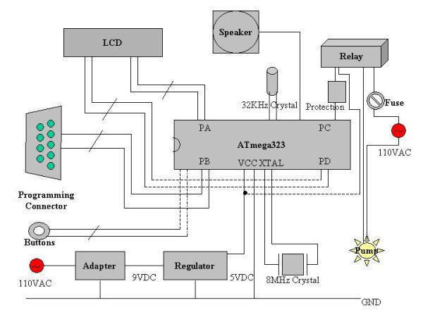
It contains the several major blocks:
- ATmega 323 is the CPU of the system.
- 5 VDC power supplier: an adaptor first transforms 110 VAC 60 Hz into 9 VDC; then a regulator keeps VCC stable at 5 VDC.
- A crystal of 32KHz is used to provide a real-time clock.
- A crystal of 8MHz is for the CPU frequency.
- A block of circuit is built for programming so that the executable code can be downloaded from a computer to the system via a serial RS-232 port.
- A LCD is used to display the time and system states.
- A speaker is used for alarming and making sounds.
- Push buttons allow a user to change the system states.
- A relay is used to control the AC of the water pump with a DC signal from the processor.
- A block of circuit is used to protect the processor since a high voltage introduced from the relay can damage the processor.
Some key blocks will be explained in detail later on.
Electronics
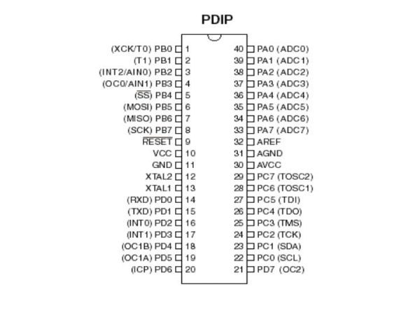
The AVR processor used in this project is an ATmega323. It has two 8-bit Timer/Counters and one 16-bit Timer/Counter. Meanwhile, it supports the real-time counter. These features satisfy the system’s demands. More detailed information can be founded in data sheets at Atmel. The following picture shows the pin configurations of the ATmega323.
The programming control circuit is shown in AVR basic system schematic. With this circuit, the code can be easily read and written by software PonyProg.
The regulator circuit uses an LM7805. A heat sink helps it cool down. This block of circuits is also shown in AVR basic system schematic.
The system has lots of functions heavily depending on a real-time clock. Thus, a 32768 Hz crystal works here. With a prescale of 128 and Timer2’s overflow interrupt service, the crystal finally offers a 32768/128/(2^8) = 1 Hz frequency. Circuits for both the RTC crystal and the 8MHz crystal are shown in AVR basic system schematic.
A 2*24 HD44780 LCD is used as a display.
A 0.2W speaker makes sound.
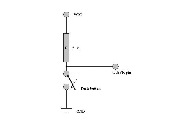
The following diagram shows how push buttons work. When the button is pressed, the output signal is connected to GND. When it is released, the output is connected to VCC. Thus, it simulates push buttons in AVR STK500 kit. Push buttons are nominally open.
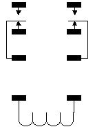
A R40-11D2-5 relay plays an important role in this project, since it is the relay that changes a control signal from the AVR into turning on or off the water pump. Its contact arrangement is shown as following.
In the system schematic as shown previously, there is an additional circuit for the relay to protect the AVR’s pins from being damaged. As we know, U=LdI/dt. There could be as large as 100 volts introduced from coils in the relay when the current flow in the coils are suddenly stopped or allowed. This high voltage can easily break through the AVR ports. In order to protect the AVR, the following circuit is used to limit the voltage applied on the AVR pins.
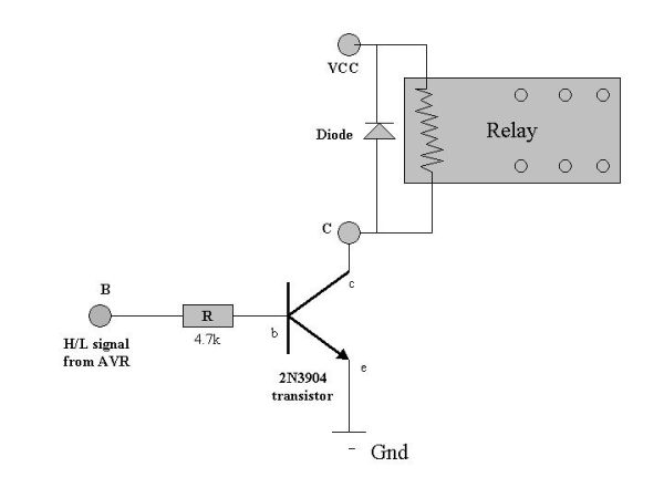
With this circuit, about 5 volts will be applied if the input control signal at B is high, which is large enough to trigger the relay.
The water pump (CAL P60) is in serial with a fuse for safety.
The speak makes sound of a certain tone when it is fed with a rectangular wave of a certain frequency in the project.
Source: Worry-Free Automatic Timed Plant Feeder