I was playing Starwars Battlefront beta on my PS4 when I noticed how loud the internal cooling fan was sounding. I thought this was normal until I did an internet search about the noise of the PS4 cooling fan. Many searches revealed that the fan is relatively quiet. This was not my experience. I also noticed how hot to the touch the case of the PS4 was getting when the fan was at “full throttle”. The case was alarmingly hot for a console. I thought something may be malfunctioning and I had to figure out what was going on.
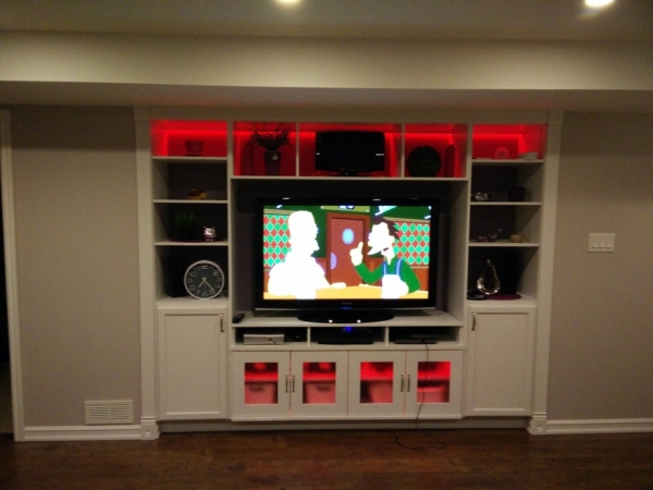
I recently finished my basement. Part of the construction was a built in entertainment system shelving unit.
I constructed three “cubbys” directly underneath the television stand. One for my Xbox 360, one for my center channel speaker and one for my PS4. Each cubby is 18 inches x 15 inches x 5 inches in dimensions. There is a one by five inch slot at the rear of the cubby to allow wires to be channeled (and heat to escape into the adjacent cubby). I figured the cubby was large enough to dissipate the heat produced by the consoles and passively exhaust it out the front into the basement room. This turned out to not be the case. A digital thermometer probe placed at the rear of the cubby indicated the air temperature around the PS4 during heavy use was as high as 118F.
I also had nowhere to put my WD TV Live Hub so it is sitting on top of the PS4. It does not generate much heat but may still interfere with good airflow.
My solution to this “overheating” problem was to purchase a third party PS4 cooling system to remove the heat. There was no cooling product that I liked online and I wasn’t sure they would give me the desired results I required. I did not need to remove heat from the PS4, I needed to exhaust the heat from the cubby. Once this was accomplished the PS4 cooling fan would not have to work as hard to cool down. I decided to design and construct my own cooling system that would be a stand alone device which could be moved to any cubby or compartment to help exhaust hot air. This cooling system would trigger on at a programmed temperature and run until another lower programmed temperature was met.
I had a blower type fan I had not used from a previous project. I was going to use it to cool the PS4 cubby. Initially, I tried to design the control system with discrete IC’s like the LM393 comparator. In practice I could not get the hysteresis window to work correctly with an elevated reference voltage so I abandoned this design for a microcontroller. For a little project like this, I decided to use a Picaxe 08M2. I thought about PWM to incrementally spin up the fan depending on the ambient temperature however my initial breadboarding tests indicated I would get good results by simply triggering the fan on and off.
The plan is to use the blower fan, a small wall wart power supply and the Picaxe with other electronics and design and build a “cubby cooler” that can be used in any confined space to remove heat or increase circulation.
Step 1: Explanation of the Circuit
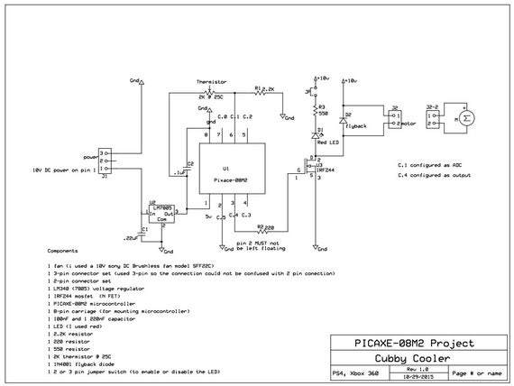
I will be temporarily using a 12 Volt DC wall wart to give the required power to the cooler. (I ordered and I am waiting on receiving a 10 volt 1 amp wall wart) to be the final power supply. The blower fan is rated for 10 volts. The higher the supply voltage the louder the fan noise so I will use the 10 volt supply to keep the fan noise down and still get plenty of air movement.
The connector from the wall wart is modified to fit the connector on my PCB. The 12 volt input voltage is regulated to 5 volts by the LM340 using two smoothing capacitors. Five volts then powers the microcontroller and the voltage dividing circuit of the thermistor and 2.2K ohm resistor. The voltage produced at the ADC pin of the Picaxe varies wrt to the changing resistance from the thermistor due to temperature changes. The software program then determines whether to send an output to a Mosfet (switch) which turns on or off, allowing the fan to run or not. A flyback diode electrically protects the Mosfet. An LED is optional. I have a jumper on it so I can disable the LED if I don’t want the light signalling that the fan has powered on.
If I was to redo this circuit I would have chosen an output pin on the Piaxe that had PWM control. This would give more flexibility in the future if this option was required. The pin I chose does not have this option. Both attached files (.sch and .pcb) were created and can be opened in PCB express software.
Step 2: Getting Started; Programming and Breadboarding.
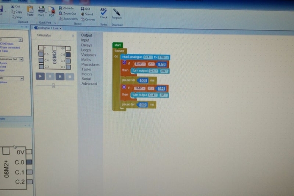
I started by acquiring readings of the temperature values involved in the cubby space by using a digital multimeter and thermistor. I then opened up my Picaxe programming software on my PC (free to download and use) and started programming. I used blocky. This is a very simple graphical programming interface, its just drag and drop. I estimated the analogue to digital values (0 to 244) and used them for set points to turn on and off the fan. I flashed the Picaxe chip with my homemade Picaxe programmer.
The next step was to breadboard the electronics. All of my electronic components other than the Picaxe microcontroller are scavenged from obsolete and discarded electronic circuit boards I have access to. If you are wondering that there may be newer or more appropriate IC’s to use, this is why. I completed the breadboarding and I tested the circuit using my Xbox 360 as the heat source because the heat exhaust port was easier to access. After much troubleshooting of my mistakes along the way, the circuit operates perfectly.
Step 3: Designing a Schematic, Layout and Constructing a PCB.
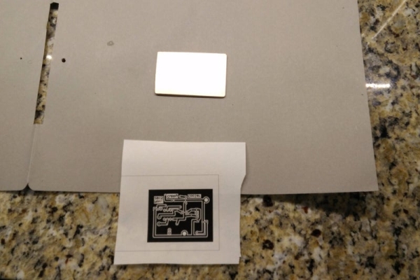
For simplicity, I have traditionally used PCB Express free software for layouts of PCB’s. I find this software has a short learning curve. I usually skip producing a schematic in favour of going straight to the layout. I would not recommend this. I created a schematic first this time which proved very useful in troubleshooting the problems I encountered. The next step was to produce a layout. The layout was printed using a laser printer and transferred to a copper clad PCB. There are many online tutorials on this step so I wont go into my method. Let me just say it took me half a dozen attempts to get a circuit board transfer that worked.
The component holes were drilled using a dremel style tool and all the components were easily solder on the board. I cut out a foam backing to be added under the pcb. This will prevent the solder points from shorting out on the metal frame of the fan.
At this point let me say that I did make a mistake on the schematic and layout. I forgot to learn my lesson which I seem to repeatedly make. Pin 2 of the Picaxe microcontroller must not be left floating or the software will not run properly. I left Pin 2 floating. The picture of the transfer on the PCB has the error however the the schematic picture and layout picture have been corrected. I had to wire a small jumper on the bottom of my PCB to ground out Pin 2, so don’t make this mistake!
Step 4: Choosing a Fan and Temperature Sensor (thermistor)
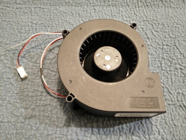
I used a blower type fan. I was able to generate performance specs of the fan. In the excel file picture I measured and plotted the current requirements and flow output in liters per minute versus the input voltage. I have access to equipment that can measure flow accurately and I used a digital multimeter to get the current.
I also had little information on the thermistor so I measured its response with respect to temperature and resistance and plotted it in an excel graph. This allowed me to plot a line of best fit and generate an equation for that line. Now I can estimate fairly accurately the thermistors resistance at a specific temperature. I wrote a function in excel to do that. Using this value I can mathematically calculate an ADC value to add into my software program. Hope I didn’t loose you with that poor explanation. Initially, I used a set point of 108F to turn on the fan and 80F to turn it off. I felt that this was still too hot of a temperature so I later changed this to 90F for on and 80F for off by reprogramming the Picaxe. This kept the cubby compartment cool however the fan operated more frequently.
Source: Xbox One, PS4, Xbox 360 Cubby Cooler; the Problem and the Solution
