Summary of A Wand Based Barcode Scanner Using Atmel MEGA32
This project developed a UPC-A barcode scanner using a low-cost wand scanner and a microcontroller, emphasizing software-based error correction over complex optics. The wand outputs TTL signals indicating black or white surfaces, and the system uses a state machine to decode bar width transitions into barcode digits. The scanner supports serial communication for retrieving product information via RS-232, emulated through a terminal interface. The design prioritizes EAN-13 barcode standards (specifically UPC-A subset) and features a multi-stage error correction mechanism to improve accuracy despite user scanning variability.
Parts used in the UPC-A Barcode Scanner Project:
- MSH-119 Wand scanner (E-bay)
- Atmel MEGA32 MCU
- LCD-64 display
- Large solder board
- LM340 regulator
- RJ-11 double socket
- 6 x 0.1uF capacitor
- 2 x 22 pF capacitor
- Trimpot potentiometer
- 16 MHz crystal
- Headers and jumpers
Introduction
Our project is a UPC-A Barcode Scanner complete with a pricing/description database interface. Our original goal for this project was to build a standard barcode scanner from scratch, but as the project evolved so had to our specification of the project. We initially sought to build a charge-coupled device (CCD) scanner, which scans the entire barcode at once. This, however, required parts beyond our budget, namely a high-resolution CCD array, as well as knowledge of optics well beyond our own. We then shifted our focus to a pen or wand style scanner, where the user drags the tip of a pen evenly across the barcode to read it.
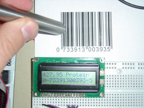
This, however still required substantial optical work. We discovered that we could purchase a dumb scanner wand on E-bay for around $10, thus our ultimate implementation. The so-called dumb wand simply gives the user a TTL output stating whether it is reading from a black or a white surface. This essentially shifted most of the design challenge from optics to software, especially error correction, which we felt was more appropriate considering the nature of this course.
The major design challenge we encountered surrounded dealing with the inaccuracy of the initial readings. Because of the small size of most barcode features, only a few samples could be taken over some of the smaller ones during a pass with the wand. This necessitated substantial error correction to attain reasonable accuracy for a given scan. The nature of the wand scanner, as even detailed by commercial producers, requires a steady and well-trained hand to scan.
Since simply reading a barcode and returning its value is not useful on its own, we also added a serial communication interface that would allow the MCU to get information from a database or other software for the particular barcode, which we emulate with the terminal.
High Level Design:
1. Idea and motivation
There was no real spark for the idea to build a barcode scanner. It just seemed like an interesting and challenging concept for a project.
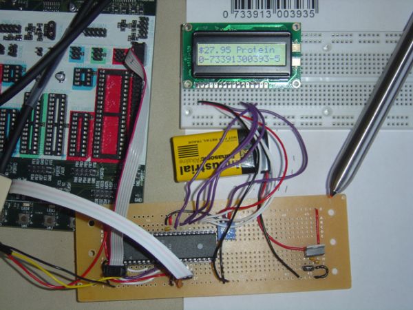
2. Design Overview
We approached our design process by working separately on two distinct fronts and merged them once each was complete and functioning in isolation: reading the barcode and decoding it.
Reading the barcode: This task centered around first learning the capabilities of our wand scanner. Its interface is simply an open-collector TTL output which reads at 5V if the scanner is over a black bar and 0V if it is over a white space. The scanner itself features a red-light phototransistor and a red LED focused through a lens. The phototransistor will detect if the light is reflected off the surface below, thus reading a white space in the barcode. The trick to reading one of these barcodes is tracking the number of white/black transitions.
As detailed earlier, each section of the barcode is guaranteed to have a certain number of these transitions, effectively clocking the scan. We used a state machine to track the transitions and detect where the wand is in the barcode. The relative widths of each segment (bar or space) in each digit section gave us the 7-bit encoding for each digit, which can then be decoded.
We approached this part of the design by first tackling the parts over which we would have complete control before introducing the uncertainty of the scanner. I began working with a standard C compiler to test code to handle the transformation of the relative widths of the bars and spaces into the 7-bit encoding by using some simulated reads. I later found out that due to code speed I would not be getting so many samples, which introduced the need for error correction.
Decoding the barcode: This task centered around understanding how the barcode was encoded in the first place. Once we understood how the barcode was encoded, it was simple to design decoding software. The decoder is written for an EAN-13 barcode. The decoding software takes in an array of unsigned characters from the scanning software and determines what digits each character represents. The decoding software then calculates the checksum and compares it to that from the decoded barcode in order to guarantee a valid scan.
3. Hardware/Software tradeoffs
We shifted most of our design challenge from hardware into software, mainly because those particular hardware challenges would have been primarily optical in nature and likely require precision equipment to which we did not have access. Had we been able to scan the entire barcode with a CCD array in one shot, we would not have had the error variable of the user dragging the wand. Had we been able to build such a scanner, our accuracy would have greatly improved. But again, after much evaluation we deemed it an unreasonable goal. To compensate for this, we had to develop a multi-stage error correction algorithm, which greatly improved the scanning success rate.
4. Standards
EAN-13 Barcode:
The barcode standard for our project is EAN-13. This is an international standard and a superset of UPC-A (The US & Canada standard). By choosing this standard for our device we make it marketable worldwide. ISBN, ISSN and ISMN are all encoded using the EAN-13 standard so our device will work on a variety of products. Also, beginning in 2005 all decoding and database systems will be required to handle EAN-13 codes, to universalize barcodes, making this standard far and away the appropriate primary choice
The EAN-13 encoding is split up into four groups:
- The Number System consists of the first two-to-three digits and specifies what country or economic region assigned the manufacturer code.
- Manufacturer Code This is a variable length unique code that is assigned to each manufacturer.
- Product Code This is a unique code assigned by the manufacturer to each of its products.
- Checksum digit. An addition digit used to verify correct scanning of the barcode.
After scanning the barcode, it must be verified as valid. This will be accomplished by calculating the checksum on the first twelve digits and comparing the output to the checksum digit. This will be extremely valuable in our testing process. We have decided that if the checksum fails then we will rescan twice before sending an error to the user. This scheme is meant to increase the accuracy of the Barcode scanner making life simpler for the human operating it.
NOTE: Due to error correction considerations, our barcode scanner will only read UPC-A Barcodes, which are a subset of EAN-13 Barcodes. This simplifies one dimension of the encoding allowing for more accurate error correction.
RS-232 asynchronous serial communication:
We used the RS-232 standard for our serial communication with the PC just as in earlier labs in the class, by hiding the the output interface through the use of the standard input/output library in C. We then implemented the input interface with a non-blocking receive interrupt mechanism, as done in in Lab 3. This serial interface served as the link for our emulated database.
5. Intellectual Property considerations
The only intellectual property consideration surrounds our use of another companys wand scanner, so our product could be marketed as a decoder for it. Otherwise all of our ideas and methods were original. The only code that was not completely original dealt with receiving characters from the USART from the Security System lab.
Program/Hardware Design:
Program Details:
For the sake of versatility there are two compile-time options, implemented through the frequent use of the #ifdef directive, built into the program: a debugging mode and a terminal interface mode, each of which makes use of the serial connection to a PC.
Debug mode: Displays a plethora of important information regarding the scan on the PC terminal. This was incredibly useful when evaluating scanning accuracy and developing error correction. By watching for trends in the errors we were able to discern patterns that directly influenced the error correction schemes, especially the favoritism toward correction to a width of four, as described earlier.
Terminal mode: This mode adds the serial interface to the terminal used to emulate a database system for the scanner. If this mode is off, the LCD simply displays the UPC number and the country of origin. When this mode is activated, the MCU sends the UPC to the terminal, which could then be used by a database to return the relevant product information. For our emulation, a user can type in the information for which it is prompted, including price and a product name, which are sent to the MCU and subsequently displayed on the screen.
The guts of the program is split into two major segments, one handling the reading of the barcode and the other decoding that data into the actual barcode and displaying the information, including that received from the terminal.
Barcode read:
We immediately recognized that we would need an organized program to read in the barcode digits piece by piece and to do so quickly to get enough data samples. This immediately suggested the necessity of a state machine driven by a compare match interrupt on Timer1 running as fast as possible, effectively running as software polling. To get optimal performance, we deactivated the register save on both the ISR and the state machine update and designed them such that they used only global variables. Therefore we needed only to save and restore the status register on each call, saving approximately 60 cycles per call.
The ISR read from the scanner on PORTB tracked both the current and previous read to watch for transitions. Upon reading the first three transitions, the scanner has finished the left guard and has moved on to the left-side digits. These digits each contain four bars/spaces, whose widths are recorded by the ISR which counts the time between each subsequent transition. Upon finishing the sixth digit, the state machine watches for the five transitions of the center guard before reading the right digits in the same manner as the left.
The barcode then finishes with a three-transition right guard bar. Because a user can abort a scan at any time by lifting the pen or stopping it, the state machine required a timeout mechanism to reset it and be ready for the next read. Because transitions are expected, the timeout check simply check to see if there has been a specified length of time since the last transition.
Once the widths have all been recorded, they must be reduced to their 7-bit encoding. So effectively the widths must be scaled down to a total width of seven. Because so few samples are taken, there is an interesting problem created by integer math; often the numbers will not work out perfectly and adjustments will need to be made. First, any width that evaluates to zero is automatically increased to one and likewise any width over four is reduced to four, since otherwise the scan would be invalid. Second, and also a consequence of integer math, if the scaled width is still less than seven, then the closest bar or space which is the next closest to the next step up is incremented; this is achieved by checking the size of remainders. This step is carried out until that total width of seven is reached.
Parts List:
| Parts List: | Cost: |
| MSH-119 Wand scanner (E-bay) | $10.00 |
| Atmel MEGA32 MCU | $8.00 |
| LCD-64 display | $5.00 |
| Large solder board | $2.50 |
| LM340 regulator | $1.00 |
| RJ-11 double socket (found) | Free |
| 6 x 0.1uF capacitor | Free |
| 2 x 22 pF capacitor | Free |
| Trimpot potentiometer | Free |
| 16 MHz crystal | Free |
| Headers and jumpers | Free |
Total: | $26.50 |
For more detail: A Wand Based Barcode Scanner