For our ECE 4760 final project, we designed and built a wirelessly programmable digital pace clock with a large format LED display and Android smartphone control and programming.
This original design achieves the functionality of commercailly available pace clocks but with an intuitive user interface that goes beyond anything that is available in the current marketplace, all at a small fraction of the cost.
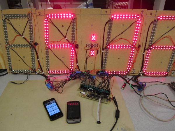
The clock runs from an Atmel ATmega32A microcontroller and a host of peripheral integrated circuits with a Bluetooth connection to an original Android smartphone application to configure swimming workouts, timing intervals, and real-time wireless control of the clock’s features.
A Background on Swim Training and Pace Clocks top
A pace clock is a large format clock used to time intervals in athletic training, most commonly in swimming or track. Modern pace clocks are large format 4-digit LED displays, with either a grid or 7-segment layout. Swimming workouts are typically organized in advance of a swim practice and include a series of different strokes and drills at various speeds and of various distances. The interval timing can be done with a single count-up clock display, requiring the swimmers and coaches to calculate the appropriate start times and estimate their pace mentally by following a clock. Alternatively, as many proactive collegiate swim coaches do, the day’s or week’s workouts may be programmed into a programmable pace clock to automatically time the swimmers’ sets. This means, for example, that the clock would either count up-to or down-from the interval time (eg. 1 minute and 20 seconds) and then move on to the next interval. This improves workout efficiency by ensuring that the swimmers start the next set on time, and that they receive accurate feedback about their performance and pacing.
An item within a workout will convey to the swimmer (usually in this order): the number of repetitions, the distance, the stroke with optional comments, and an interval. For example, a swimmer might see the following item in a day’s workout:
This indicates the swimmer must swim 100 yards (or meters, depending on the pool) of the butterfly stroke 10 times, on an interval of 1 minute and 50 seconds, with the first half of each 100 being a butterfly drill and the second half being the standard, full stroke. A pace clock makes this timing possible, and a programmable pace clock makes it easier by counting up to 1:50 (which allows swimmers to see their pace as they finish each 100) or down from 1:50 (which allows swimmers to quickly see how much time remains before they must start the next 100 fly).
Swimming workouts are structured with repetition, loops, and variable intervals, basically a series of the above items that may appear as the repetends of loops. Loops may also appear in the repetends of loops. There are thousands of workouts which can be found online for further clarification.
Pace clocks are expensive and can be cumbersome to use for those not willing to learn their operation and programming method. One of the leading companies selling pace clocks is Colorado Time Systems. A wirelessly programmable pace clock such as the one we have designed and built costs roughly $900-$1400, not including the programmer which costs $440 and is required for programmable workouts. There are additional features on these systems which we did not intend to implement. These may account for some of the difference in expected price between our design ($75 maximum) and the $1k-$2k commercial systems. These differences include battery operation, multiple screen-controlling with a single ($440) controller, and standard interfacing with a much larger product line, including race-accurate timing pads for competition. Many swim teams, particularly in summer swim leagues, cannot afford such elaborate timing systems and cannot justify a fully integrated race timing solution since they rent time at public pools and use rather low-tech timing solutions for races: parents equipped with stopwatches.
Christaina DiMaria, Cornell Swim Team Captain
By designing a wireless, programmable pace clock in the price range of smaller swim programs, and enabling its wireless control through a Google Android Smartphone App, we have produced a viable product with a much broader buyer market than the currently available commercial systems. To our knowledge, no such product exists at this time. The coupling of a Android-based controller (and its intuitive, simple interface) with reliable and cost effective microcontroller operation can vastly improve the cost effectiveness and usability of these training tools to make pace clock timed workouts accessible to more athletes.
High Level Design top
Overview
Our project brings together a wide range of hardware and software design experience: from bit level inter-chip communication to processing our compact, original instruction set, to managing user interactions wirelessly in real time, to designing an intuitive user interface for configuring and interacting with the pace clock on an Android smartphone.
Standards
A variety of standards are used to implement communication between peripheral devices, and we use a large fraction of the peripherals available on the ATmega microcontroller. Communicating with the LED drivers is achieved using the SPI interface and a host of other connections required by the TLC5940 devices. These LED drivers are complicated and capable of 12-bit PWM current sinking using an external clock, as well as 6-bit dot-correction tables with persistent and SRAM storage registers. As a result, there is a lot of data formatting and transmitting required to get them to function, even if we only need DC illumination. Communication with a real-time clocking chip uses the I2C/TWI standard (I2C is a proprietary name owned by NXP); the chip itself has many configuration and data registers that can be read and written to perform clock and calendar timing operations. We wrote drivers with simple interfacing functions for both the LED drivers and the clocking chip. Our software uses Peter Fleury’s open source I2C/TWI library, available from his website referenced at the bottom of this page. Communication with the radio module uses the microcontroller’s onboard USART peripheral unit (asynchronously, so the ‘S’ can be dropped). The radio module itself uses the Bluetooth standard (Bluetooth is a proprietary name owned and managed by the Bluetooth Special Interest Group). Configuring the radio module can be done locally by the microcontroller or remotely from a Bluetooth equipped computer. The Android smartphone uses several levels of software abstraction to communicate with its Bluetooth hardware, and Google’s API for Android App Development is used to design a useful configuration and remote control interface to our pace clock for an Android device.
Intellectual Property
Although we used a knowledge of Colorado Time Systems pace clocks in designing our project, we do not believe our work infringes on any of their patents (or other patents). In the References section, we have linked two patents that are in the same field, but not very similar to our project. The Colorado Time Systems patent refers to a modular display system which is reconfigurable and useful for changing a large display’s format with cover panels and software/hardware to use it correctly. Colorado Time Systems sells wirelessly programmable pace clocks, but with different functionality and methods of programming; notably–using a physical push-button based programmer. The Swimnetix patent application in the References section also involves a programmable clock, but involves workout programming and monitoring via physical interaction with the swimmer though touch-pads in the pool and a wearable heart-rate monitor. Additionally, it is for a small waterproof unit that sits at the end of a swimmer’s lane, not a large format display that is used by a whole pool of swimmers simultaneously (as ours is). We believe no one has sold or patented a pace clock with Bluetooth control like ours, and have not found anyone selling a smartphone controlled pace clock.
Hardware and Software Tradeoffs
One of the biggest design considerations when starting this project was the trade-off between hardware and software. We adopted an embedded system architecture inspired by microfabrication equipment (and probably used in a lot of industrial machinery too), that splits setup and runtime operation between software and hardware. The idea is that configurations and settings are done on a software-heavy very capable computer (the smartphone, in our case), and then data is formatted and sent to microcontrollers in a simplified format that the microcontroller can interpret. Execution of the task is then performed by the microcontrollers with only a reduced set of interactions available to the user (for example, the available operations could be limited to “stop”, “next”, “shut everything down”, and little else). The obvious benefit is that the user interface can be graphical and doesn’t need to be executed by the microcontroller. The real reason this is commonly used, however, is for stability. Critical operations are managed by the microcontroller firmware, which is simpler than graphics software, closer to the hardware signals, and hopefully more stable than a PC with an operating system and several concurrent programs and services running. In our project, the user configures routines on the smartphone interface, then switches to a simplified “remote control” tab with only 6 buttons. One of them uploads the data which the microcontroller stores in EEPROM (so the routines will still be stored after unplugging the pace clock), another button powers the clock on and off, so that leaves only 4 that are used to navigate through the instructions and timing intervals. The interface is clean, simple, and uses large buttons with limited and strictly defined functionality. The benefits of this architecture are many, and we touch on them throughout this report, but perhaps most significantly is that this method makes it easier to learn how to use the pace clock and the remote control can be simpler and less expensive.
High Level Block Diagram
More than anything, this project is about peripherals, and connecting hardware with software and software with human interaction in an intelligent, efficient way. The ATmega microcontroller has more than enough computation power to manage the pace clock’s large-format display, a connection to a real-time clock/calendar chip, and the user interaction that comes in over Bluetooth. Today’s smartphones have an enormous computational power that exceeds what is necessary to control the clock and allow the user to efficiently manipulate its behavior to aid in athletic training.
User Interface
The most important part of this project is that the clock acts in the way the user expects it to act. The user knows what he or she wants—a measure of time in customizable way that a simple clock cannot provide. The microcontroller software and the Android App software should act in intuitive ways to accomplish the timing intervals and workout scheduling that the user specifies.
Fundamentally there are two parts to the user control. The first is intended to mimic the workout design that a swim coach would write down (or program in some software platform if they have such technology). This means specifying a series of strokes, drills, and intervals, with programmatic and spontaneous pauses for coaching or for the swimmers to rest. On our system, the user can organize many intervals and instructions for the clock to execute into 32 routines on an Android smartphone. Each timing interval can include a message that specifies which strokes or drills to do. These routines are compiled and sent over the phone’s Bluetooth connection to the microcontroller managing the clock. The clock saves these routines permanently until a new set of routines (perhaps the following week’s workouts) are uploaded.
The second interface is much like a television remote control, and indeed, could be implemented as one without much difficulty. It purposefully pares down the available commands to just 5 buttons (in addition to the upload button used previously), allowing the user to skip through the uploaded routines, pause timing intervals, and jump between different workouts or routines on the fly (as is often necessary when coaching a real swim practice). The available commands are implemented as large buttons on an android screen (see the Mobile Application section under Software for more detailed description).
During execution, the user may change the clock’s state asynchronously with the 6 buttons or when prompted by the clock’s interpretation of an instruction that needs user input. For example, the microcontroller handles the user: setting times in the clock-set mode or the scheduled-start-time mode, skipping through intervals and loops, restarting intervals, pausing/resuming, and selecting routines in an arbitrary order. Powering on/off of the system is also accomplished over the Bluetooth remote, as is uploading. In a powered-down state, the system consumes significantly less power than with the screen on, and the electronics are put in low power modes with the exception of the Bluetooth module which must still respond to power-on commands from the user. The following table illustrates the available transitions between the pace clock’s states, depending on the current state. It specifies the behavior for any button press at any time.
One of the major benefits of our two-tier interface (upload; then remote control to execute the uploaded information) is that it allows a division between high-cost high-complexity interfaces—such as the routine configuration utility—and low-complexity interfaces—such as the remote-control screen used after uploading the day’s or week’s workouts. This allows the lower-complexity controller to be much lower cost, if desired. For example, any garage door opener with a handful of buttons or a Universal TV remote could be interfaced with the microcontroller to control the execution of the instructions and data uploaded from a more complex system. Not everyone has an Android smartphone, so wireless uploading could be done from any computer including a nearby desktop, then the user could control the clock with a simpler, cheaper remote control.
Note that the pace clock does not need to be controlled using an Android device because it specifies an open-source protocol for uploading data and manipulating the execution of its instructions, therefore any variety of devices at a wide range of price points (from commercial timing systems to garage door remotes) could be made to control the pace clock’s operation. The Android application was designed to take advantage of an intuitive user interface for the high customizability of our pace clock as well as its ease of distribution. See the next section for a specification of the instructions and their behavior in more detail with respect to how the clock reacts to a particular instruction.
A Compact Instruction Set
The operation of the interval timing is managed by interpreting a com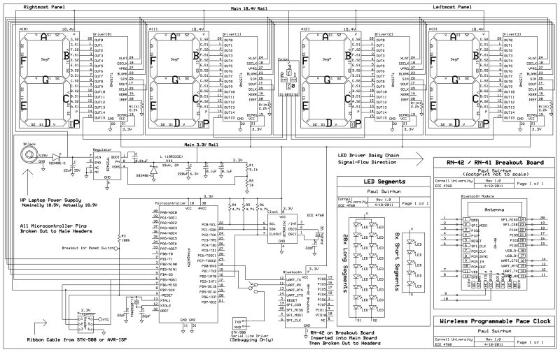 pact instruction set which we have specified. A variety of instructions are available to implement all the necessary functions of a programmable pace clock. The full instruction set is available here, and a summary of the functionality is shown below. The user essentially programs these instructions in the routine-configuration tab of the Android App. Instructions and timing interval data are stored in the persistent EEPROM memory, and interpreted by the microcontroller when parsing through during normal operation. Compactness is key, since our microcontroller has only 1024kB of memory. All instruction-format items are 1-byte and all timing-format items are 2-bytes (one byte for minutes, one byte for seconds). Compiling from the graphical user interface to the 1024kB file is accomplished by the Android App, with a few modifications from what the user sees in the configuration tab. These differences are: 1) A routine prompt instruction precedes all other data, 2) A jump to routine 1 follows the last routine, and 3) A routine prompt instruction is placed at the end of the body of every routine. To get around (3) and advance to the next routine automatically (without prompting for input after completely parsing a routine), the user simply needs to put a jump instruction as the last entry of a routine.
Parts List:
| Item | Comment |
|---|---|
| Free PCB | For PCB Design (Eagle is only free for small boards) |
| Circuit People Gerber File Viewer | Excellent online tool with selectable size downloads |
| Photoshop or Other Image Editing Software | For image resampling, scaling, and printing |
| Drill Press | Holes can be drilled with sufficient accuracy by hand. |
| Circular Saw | For cutting the fiber board and/or other wood enclosure |
| Jigsaw with tile/glass abrasive blade | Required to cut FR4; or use a shear/guillotine. |
| Hobby/Exacto-Knife with sharp blade | Essential for fixing shorts/problems on patterend PCBs |
| Tungsten Carbide “Wire Size” Drill Bits | Drill Bit City #80 – #56 Gauge, retipped ones work great |
| Anhydrous Ferric Chloride | Cheap (ebay) and reusable (does not degrade) |
| Paper Towels, Newpapers, Cardboard | To clean up chemical tanks and any spills |
| Plastic Etch and Rinse Tanks/Containers | Should have flat bottoms to minimize liquid required |
| Nitrile Gloves | To protect you from the Ferric Chloride |
| Plastic tongs, hook, and/or mixing stick | Ferric chloride etches all metals, even stainless steel! |
| Scissors | To cut out the PCB design |
| Acetone | To clean PCBs before iron-on, and to remove toner after |
| Green Scotch-Brite Pad | For cleaning/abrading copper before ironing on |
| Window cleaner | To clean PCBs after scotch-brite, which leaves particles |
| Old Clothing Iron | Water removed, hottest setting, may get ink on it! |
| Glossy Magazines | Cheap, uncrinkled, non-recycled, glossy, thin paper |
| Samsung Laser Printer | Factory Brother ink and DIY refill inks do not work! |
| Wire Cutters and Strippers | Many PCB connections made on unprinted side |
| Soldering Iron and Lead Solder | ZD-929C from MPJA. 1/32″ tip, plus 1/64″ tip for RN-42 |
| Electrical Tape | For wrapping connections to the screen |
| Heatshrink and Heat Gun | (I didn’t use these, but highly recommended over tape) |
| Solder Flux, Flux-Pen, or Paste | (I didn’t use these, but would simplify RN-42 soldering) |
| A Good-Quality Digital Multimeter | Absolutely indispensible. Should have audio-out for low-R. |
For more detail: A Wireless Programmable Pace Clock Using Atmega644