Introduction
The tags used to monitor wildlife can either be passive or active. Passive tags simply identify an individual, whereas active tags may send out a radio beacon or even collect data. These active tags, more commonly referred to as “bio-loggers”, are typically battery powered, and thus have limited life. This is especially true for birds given their limits on payload capacity. We are interested in extending the life of these tags by harvesting energy from the bird or the ambient environment, and using it to recharge the battery. This stored energy could then be used to collect environmental data, location data, possibly take in-vivo physiological measurements for the bird, and transmit data. For this project, we are interested in developing the circuitry and the microcontroller (MCU) programs necessary to indefinitely extend the lifetime of a battery powered MCU system.
High Level Design
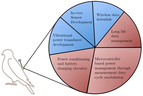
To develop the bio-logger, various subsystems need to be developed and integrated. The main subsystems are the microcontroller, power management system, and sensor suite. For this project we are focusing on developing the microcontroller and power management systems as seen in Figure 1. We will use this system as a basis for future added functionality that will include a sensor suite and piezoelectric harvester.
We have chosen to focus our efforts on developing the microcontroller code and electronics necessary for a system to monitor the state of its battery and modulate the instrument measurement duty cycles such that the system does not use more power than what is being harvested from the environment. To do this, we focused on three areas: power conditioning and battery charging, the microcontroller code for managing microcontroller operation based on the battery state, and the microcontroller code necessary for managing large data sets. For each of these sub-tasks, we asked specific questions at the outset of the project, with the intention of answering them at the conclusion. These were:
- How do you charge a battery, or array of batteries from multiple sources including high voltage AC (piezoelectrics) and low voltage DC (solar)? What voltage conditioning is necessary? What charging electronics are necessary? How can you regulate the battery voltage to a level that is acceptable to all circuit components in use?
- Can a microcontroller monitor the state of its own battery and modulate its own operation based on the state of charge? What is the lowest amount of power that the MCU can draw? Can the system keep track of the date and time when the MCU is in a low power mode?
- How can the system store the logged data for extended periods of time when the system loses power? How can the memory be used to help the system understand its own state? How should data points be logged such that data is not overwritten?
With these questions in mind, we were able to begin development of each of these sub-components. The power conditioning and battery charging circuitry was developed in parallel with the microcontroller and data designs. This allowed for independent debugging of the systems prior to system integration. Once both systems were functional, system level testing commenced.
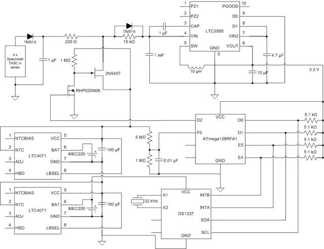
A high-level view of the components used in this project, and those expected to be incorporated at a later date as part of research, can be seen in Figure 2. In this figure, we show the major components of the power and data management system. Our project uses an Atmega128RFA1 microcontroller as the system hub. This is a more capable MCU than the Atmega644 used in class. It uses less power, has a wider array of peripherals, and most importantly, has an integrated 2.4 GHz radio that we can use in the future for wireless downlinking of the data. We use Inifite Power Solutions Thinergy thin film batteries as an energy storage source and Spectrolab, 30% efficient GaAs, TASC solar cells. Finally, one of the most important components in the system is the Maxim DS1337 low-power external real-time clock. Because the bio-logger is essentially a small-scale data acquisition system, it is critical that the time of each measurement be known. And because these systems are expected to operate over the course of years, the system needs a clock source that is continuous from the date of deployment. We have chosen this clock because it is extremely low power, and as such, allows the system to keep track of time over the course of years, assuming the batteries are occasionally charged. Even without charging of the batteries, one fully charged Thinergy MEC201 battery could power the clock for approximately 25 days. Because this clock was designed to use such low power, it does almost no conditioning of the time registers. We the time read over the I2C bus must be converted using software to a typical Gregorian date. This is one of the major tradeoffs in this system between hardware and software. We were required to make more complicated code to deal with simple, but highly efficient hardware. Another tradeoff between software and hardware for our system, although in the other direction, is using a battery charging/discharging control I.C. to protect our batteries. While the same functionality could be achieved using battery voltage measurements with the MCU, the long sleep cycles desired for this system would leave the battery completely unprotected during this time if it were to be done using software.
While neither specific patents, nor standards could be found pertaining to self-charging bio-loggers, there are companies that produce battery powered tags. One such company is Wildlife Computers. They produce a variety of wildlife tags, all of which are powered from large batteries. Four of their tags are shown in Table 1 for reference. These tags all have lifetimes that extend out close to, or more than a year, but their mass is approximately 1-2 orders of magnitude too high for use on most bird species. Our system is designed to be extremely light-weight, and will have lifetimes that far exceed those specified for these systems.
Hardware Design
Power System Design
To provide power to the ATmega128RFA1 MCU, two different sources are used: solar and battery power. The configuration of the power circuit used for this system was taken from the combination of example circuits shown for the use of the LTC4071 battery charger I.C. (will be discussed below) in its data sheet, which can be found linked at the end of this document. The Spectrolab’s TASC solar panels have the ability to directly power the MCU and recharge the Infinite Power Solutions MEC220 batteries. At their maximum power output, each of the panels can produce 2.19 V at 28 mA. The MEC220’s have a voltage rating of 4.1 V, however, and two TASC solar panels must be connected in series to achieve the necessary voltage level for one battery. The power from both of these sources is conditioned using the LTC3588 Piezoelectric Energy Harvesting Power Supply. While we are not performing piezoelectric energy harvesting with this system, future systems could require that functionality and the LTC3588 can accomodate DC energy sources as well, making it very versatile and applicable to our system. To produce the 3.3 V supply voltage for powering the MCU, the LTC3588 requires at least 5.05 V to initiate its output. Therefore, a stack of two of the MEC220’s in series is required to provide the necessary voltages for the LTC3588. Also, now that the system requires two MEC220’s in series, creating a total battery stack maximum voltage of 8.2 V, it also requires 4 of the TASC solar panels in series for the panels to be able to recharge the batteries.
Each of the MEC220 batteries is protected from over-charging/discharging using an LTC4071 Li-Ion/Polymer Shunt Battery Charger System with Low Battery Disconnect. This chip rails the maximum voltage seen by the battery to the 4.1 V specified by the MEC220 by shunting energy, protecting it from over-charging. The chip also completely disconnects the battery if its voltage goes below 2.7 V to prevent it from being over-discharged. As Figure 4 illustrates the results of the low battery disconnect behavior of the LTC4071. In this plot, four separate batteries are fully discharged, each using a 10 kΩ load. The two red curves show the dicharging of the MEC220-3S’s (their standard batteries) and the two blue curves the MEC220-4P’s (the performance versions). First, we can see the difference in the reported capacities of the two different versions of the cells as the MEC220-3S is listed at 300 μAh and the MEC220-4P at 400 μAh. Next, it is clear that any two cells, even from the same line, can not be expected to have exactly the same capacity. This difference is more apparant with the standard cells than with the performance cells.
The blue curve shows the 3.3 V output of the LTC3588, which cuts out once the battery stack voltage drops to below the worst-case 3.9 V specified to continue the 3.3V output. The effects of the different battery capacities can be seen by noticing that this drop occurs when the battery stack voltage is still above 6.0 V. Theoretically, if each of the LTC4071’s disconnects the battery when it reaches 2.7 V, then we should see operation down until 5.4 V. However, if one of the batteries reaches 2.7 V significantly before the other, it is locked out and we experience a 2.7 V drop in voltage for the entire battery stack. If the other battery’s voltage is below 3.9 V at this time, then the LTC3588 can no longer sustain its output. This significantly reduces the range of expected voltages for the battery stack during safe periods of operation as well as the overall usable energy the batteries can store.
The remaining functionality of the system hardware involving the power system revolves around the MCU communicating with and controlling the battery stack. For lithium-ion/polymer batteries, the current state of charge (S.O.C.) can be approximated quite accurately using the open-circuit (O.C.) voltage of the cell. To measure the actual O.C. voltage of the cell, not only must it be disconnected from the load, but the cell must be allowed to reach a steady-state. After the load is initially removed, the voltage rises by an amount and at a rate dependent on the load characteristics as well as the battery chemistry and capacity. To this end, a normally-on switch is added at the top of the battery stack to disconnect it from the solar cells and the LTC3588. Due to the significant difference between the 3.3 V logic-high output available from the MCU and the voltage expected from both the sources and batteries, a level-shifter topology is adapated. Also, as we do not want the batteries to be permentantly locked out if the MCU loses power, the switch has to be “Normally On”.
The LTC3588 requires a capacitor to be placed between its VIN pin and ground. When the battery stack is disconnected to measure the O.C. voltage of the cells and estimate the S.O.C. of the batteries, the MCU power is being provided from this capacitor. So, this capacitor size depends on the length of time where the battery is completely disconnected for each one of these measurements. However, as Figure 7 shows, this capacitor is drained whenever the MCU is in its active state, not just when the battery stack is disconnected. Therefore, the input capacitor has to be sized such that its voltage does not drop below the worst-case 3.9 V required for the LTC3588 to continue its 3.3 V output during any of the MCU operations. This behavior can be understood by noting the differences in discharge characteristics of a battery as compared to a capacitor. Batteries can provide more constant-voltage, low-power loads for long periods of time. This is due to the chemistry of the cells themselves. Capacitors are able to provide power at significantly higher frequencies and can therefore deal with the sudden shifts in power draw caused by shifting in and out of sleep cycles. Therefore, even though the batteries possess the energy to fully power the MCU during its active cycle, the input capacitor is drained first as it is the more readily available source. As a result, to provide power for the 380 ms the MCU is active during each of its operation, a 1 mF capacitor is required.
Parts List:
| Component | Manufacturer | Part Number | Vendor | Quantity | Unit Price |
|---|---|---|---|---|---|
| Microcontroller | Atmel | ATmega128-RFA1 Development Board | Sparkfun Electronics | 1 | $54.95 |
| External Real-Time Clock | Maxim | DS1337 | DigiKey | 1 | $2.46 |
| 32 kHz Crystal | CFS206-32.768KEZB-UB | Citizen Finetch Miyota | DigiKey | 1 | $0.49 |
| Li-Ion/Polymer Battery Charger | Linear Technology | LTC4071 | DigiKey | 2 | $4.92 |
| Thin-Film Micro-Energy Cell | Infinite Power Solutions | Thinergy MEC220-4P | DigiKey | 2 | $14.43 |
| Thin-Film Micro-Energy Cell | Infinite Power Solutions | Thinergy MEC220-3S | DigiKey | 2 | $9.02 |
| Energy Harvester Breakout | Linear Technologies | LTC3588 | Sparkfun Electronics | 1 | $29.95 |
| High Efficiency GaAr Solar Cells | TASC | Spectrolab | Spectrolab | 4 | $2.50 |
| Parts Total | $154.59 | ||||
| Labor | Slave | Graduate School | Cornell Sibley School of Mechanical Engineering | maximum reportable 400 man-hrs | $30/hr |
| Total | $12,154.59 |
For more detail: Self-Reliant Power and Data Management System Using Atmega644