After I wrote several articles about using ATmega microcontrollers (DIP40) in Arduino environment I had some feedback that I was asked how to be effectively put into operation this project. As I came into the Arduino world from classical microcontrollers development world, I have not found necessary to elaborate a method or hardware project for this.
Meanwhile I realized that in Arduino world as there are many users who not have a background in digital electronics / microcontrollers development. This is the great advantage of Arduino, it is so easy to use that even if someone have no knowledge or experience with electronics or programming, can get a simple project running in hours (or minutes).
Personally, I use the Arduino as a platform for experimentation. Even if most of the times I bypass hardware “abstraction layer” (and working directly with microcontroller hardware) I continue to use the Arduino IDE because is so simple(and fast) to start experimenting with different algorithms or techniques to control various peripherals.
I must admit that sometimes I use Arduino IDE as a replacement for AVR Studio, as long as USBASP is well supported. So I think that this project will not be useless, although there are many similar projects, each with advantages and disadvantages.
Advantages:
- Can be used with DIP40 ATmega Microcontrollers: ATmega16, ATmega32, ATmega644, ATmega1284, ATmega1284P
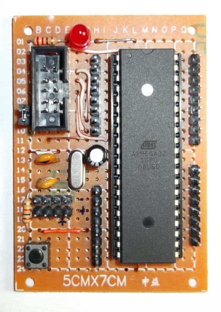
- Thru-hole components / easy to solder
- Can be used with Arduino IDE (or other IDE / programmer / compiler )
- Include filtering of AVCC for better analog input.
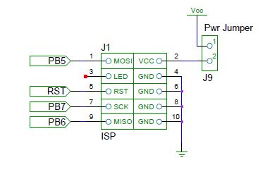
- Include 10pin ISP connector / easy to use with USBASP (or another compatible programmer)
- More freedom in the choice of connections with external modules
- … I almost forgot … price…
Limitations:
- No bootloader (limitation or advantage, depends on how you look at). However a bootloader can be easily added (…some hardware is required)
- No standard Arduino footprint. (We can not plug directly standard shields, but can still use them in more traditional way, with jumper wires)
Step 1: Comparison
Here is a comparison between various common microcontrollers (DIP40 package) from ATmega family.
Please note that ATmega328P and ATmega2560 are not DIP40. I put them here for comparison (ATmega328P ~ Aruino Uno / ATmega2560 ~ Arduino Mega 2560).
I also emphasized column for ATmega1284 / 1284P, this is the most capable microcontroller for ATmega in DIP40 package (at least at the time I wrote the article).
Step 2: Schematic
At first I make schematic to illustrate minimum requirements to start an ATmega microcontroller at full speed.
In circuit design I used both specific Atmel datasheets and Application note AVR042: AVR Hardware Design Considerations. I tried to follow them as much as I could without unnecessarily complications. Also I used Application note AVR910: In-System Programming.
At this step it is attached also pdf version of schematic.

Step 3: Schematic detail: Power
“Looking at the datasheet for an AVR microcontroller, one can be fooled to believe that power supply is not critical. The device has a very wide voltage range, and draws only a few mA supply current. But as with all digital circuits, the supply current is an average value. The current is drawn in very short spikes on the clock edges, and if I/O lines are switching, the spikes will be even higher. The current pulses on the power supply lines can be several hundred mA if all eight I/O lines of an I/O port changes value at the same time. If the I/O lines are not loaded, the pulse will only be a few ns.
This kind of current spike cannot be delivered over long power supply lines; the main source is (or should be) the decoupling capacitor.” – Application note AVR042: AVR Hardware Design Considerations
Power supply of AVR microcontroller consists of two sections:
This kind of current spike cannot be delivered over long power supply lines; the main source is (or should be) the decoupling capacitor.” – Application note AVR042: AVR Hardware Design Considerations
Power supply of AVR microcontroller consists of two sections:
- Digital supply: (Pin 10 = VCC and Pin 11 = GND)
- Analog supply: (Pin 30 = AVCC and Pin 31 = AGND)
Power can be supplied from ISP connector (when J9 is on) or from power headers (J6 -VCC and J7-GND)
Decoupling capacitor C3 should be placed as close as possible to the supply pins.
AVCC is filtered with L1(10uH) and C4(100nF) for better noise immunity of ADC section. This filter can be omitted If you consider that ADC will not be used (or analog input accuracy does not matter too much).
Power LED and it’s limiting resistor is optional (However it’s good to have a visual feedback when the circuit is powered).
Step 4: Schematic detail: Quartz
“Most AVR MCUs can use different clock sources. The optional external clock sources are Clock, RC oscillator, crystal or ceramic resonator. The use of crystals and ceramic resonators are in some designs causing problems due to the fact that the use of these clock sources is not well understood.
[…]
Finally, the importance of the physical location of the resonator in relation to the AVR should be stressed. Always place the resonator as close to the AVR as possible and shield the resonator by surrounding it with a ground plane. ” – Application note AVR042: AVR Hardware Design Considerations
[…]
Finally, the importance of the physical location of the resonator in relation to the AVR should be stressed. Always place the resonator as close to the AVR as possible and shield the resonator by surrounding it with a ground plane. ” – Application note AVR042: AVR Hardware Design Considerations
Step 5: Schematic detail: Reset
“The RESET pin on the AVR is active LOW, and setting the pin LOW externally will thus result in a reset of the AVR
[…]
The reset line has an internal pull-up resistor, but if the environment is noisy it can be insufficient and reset can therefore occur sporadically. Refer to datasheet for value of pull-up resistor on specific devices.
[…]
Connecting the RESET so that it is possible to enter both high-voltage programming and ordinary low level reset can be achieved by applying a pull-up resistor to the RESET line. This pull-up resistor makes sure that reset does not go low unintended. The pull-up resistor can in theory be of any size, but if the AVR should be programmed from e.g. STK500/AVRISP the pull-up should not be so strong that the programmer cannot activate RESET by draw the RESET line low. The recommended pull-up resistor is 4.7kOhm or larger when using STK500 for programming. For debugWIRE to function properly, the pull-up must not be smaller than 10 kΩ. To protect the RESET line further from noise, it is an advantage to connect a capacitor from the RESET pin to ground. This is not directly required since the AVR internally have a low-pass filter to eliminate spikes and noise that could cause reset. Applying an extra capacitor is thus an additional protection. However, note that this capacitor cannot be present if debugWIRE is used.“ – Application note AVR042: AVR Hardware Design Considerations
C1 and R1 values are not critical. I use values from Atmel documentation.
C1 value (if present) should be between 10nF and 100nF
[…]
The reset line has an internal pull-up resistor, but if the environment is noisy it can be insufficient and reset can therefore occur sporadically. Refer to datasheet for value of pull-up resistor on specific devices.
[…]
Connecting the RESET so that it is possible to enter both high-voltage programming and ordinary low level reset can be achieved by applying a pull-up resistor to the RESET line. This pull-up resistor makes sure that reset does not go low unintended. The pull-up resistor can in theory be of any size, but if the AVR should be programmed from e.g. STK500/AVRISP the pull-up should not be so strong that the programmer cannot activate RESET by draw the RESET line low. The recommended pull-up resistor is 4.7kOhm or larger when using STK500 for programming. For debugWIRE to function properly, the pull-up must not be smaller than 10 kΩ. To protect the RESET line further from noise, it is an advantage to connect a capacitor from the RESET pin to ground. This is not directly required since the AVR internally have a low-pass filter to eliminate spikes and noise that could cause reset. Applying an extra capacitor is thus an additional protection. However, note that this capacitor cannot be present if debugWIRE is used.“ – Application note AVR042: AVR Hardware Design Considerations
C1 and R1 values are not critical. I use values from Atmel documentation.
C1 value (if present) should be between 10nF and 100nF
For more detail: ATmega DIP40 Minimal Board