Summary of Getting Started With the ATMega328P
This article guides readers on building a basic ATMega328P microcontroller circuit to blink an LED. It highlights the chip's low cost ($4) and C++ compatibility, detailing the assembly of hardware components like capacitors, resistors, and a quartz crystal clock. The guide covers software setup using WinAVR and specific command-line instructions for programming the chip via a USBTiny programmer, ensuring the device operates reliably with the new clock speed.
Parts used in the ATMega328P Circuit:
- (2) 0.1 µF 50V Ceramic Capacitor
- (1) 0.1 µF Ceramic Capacitor
- (1) 16MHz Quartz Crystal Clock
- (1) AVR ICSP Programming Adaptor
- (1) ATMega328P
- (1) LED 5mm (any color)
- (2) 330Ohm Resistors
- (1) USBTiny AVR Programmer
- Jumper Wires
- WinAVR Software (Programmer’s Notepad)
In the Internet of Things movement, people across the globe are connecting their stuff – TVs, pets, even houseplants – to the internet and transmitting all sorts of data.
If you’re going to be a part of that movement, or want to dabble in creative prototyping on a budget, it’s important to get to know our little friend:
The ATMega.
The real benefit of using this microcontroller is that it’s only $4 US, whereas many other micro-controllers are 10X that price. It can also be easily programmed in the universal programming language, C++. The ATMega is also equipped with a decent amount of memory for any project.

Step 1: Application for the ATMega
Applications for the ATMega continue to grow across the global tech sphere. Today, it’s mostly used in simple machines to receive, interpret, and output information. You may have seen the ATMega used in small machines like RC cars and robots. It can make them autonomous and allow these devices to get from point A to point B on their own.Thus, for its size and its cost, this is a powerful little device. Jaycon Systems is here to equip you with the know-how to put it to use!
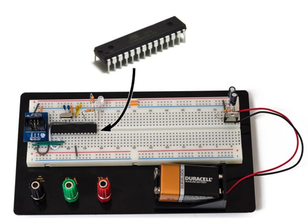
For our demo, we’ll use the basic 5V power supply created by founder and friend, Jay. Above you can see a picture of the circuit.
Step 2: Materials
Hardware:
(2) 0.1 µF 50V Ceramic Capacitor
(1) 0.1 µF Ceramic Capacitor
(1) 16MHz Quartz Crystal Clock
(1) AVR ICSP Programming Adaptor
(1) ATMega328P
(1) LED 5mm (any color)
(2) 330Ohm Resistors
(1) USBTiny AVR Programmer
Jumper Wires
Software:
WinAVR [specifically, Programmer’s Notepad]
Step 3: Set-up
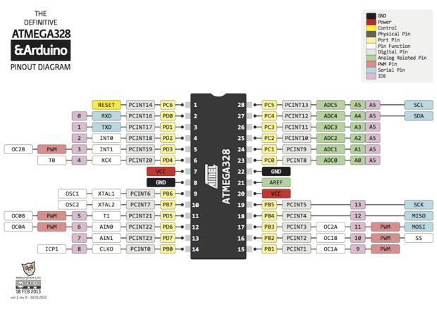
The ATMega328P is a microcontroller with 23 IO pins, two 8-bit internal clocks, and 32kB of flash memory.
To begin, notice the notch that indicates the direction of the chip — and the dot that indicates Pin 1. All pins that follow suit are in regular numerical order. If you are having trouble with the layout, check out the ATMega328P Datasheet for more information regarding the connections, and the ATMega’s abilities.
Step 4: Set-up – continued
Add a wire from Power to Pin 7 (Power) and a wire from Pin 8 to Ground.
Then, add the 0.1µF Ceramic Capacitor to Pin 7 and Ground.
Step 5: Set-up – continued
Add a LED to the first available row next to Pin 1 that is not already being used by the ATMega.
Add a 330 Ohm Resistor from Pin 1 to Power. Pin 1 is the reset pin.
Then, add another 330 Ohm Resistor from Pin 4 to the row that the LED is connected to.
You have now powered the LED.
Note: The power applied from the Resistor to Pin 1 controls what “LOW” should be so the ATMega doesn’t constantly reset itself. The LED also needs the resistor so the ATMega doesn’t kill the LED.
Step 6: Set-up – continued
The ATMega’s clock is slow and unreliable because it’s not constant.
Let’s add a crystal clock that will speed it up and make the ATMega more reliable.
Add the Quartz crystal clock to Pins 9 and 10. Then, add a 0.1 µF 50V Ceramic Capacitor from Pin 9 to Ground, and another one from Pin 10 to Ground.
(Note: It’s important to not power the ATMega with the clock already installed unless it has been flashed first.)
Step 7: Set-up – continued
You now have a working circuit, and need the programmer.
Solder the programming adapter together and place it on the board.
Make sure that you place parts in the correct direction, and be careful handling hot tools.
Step 8: Set-up – continued
The next step is to wire the programming adapter.
You can take any path to wire it in, as long as you use the correct pins.
Optional: If you are going to power your ATMega with the programming adapter, then wire from the “GND” and “+5V” pins on the adapter, across to the power rails.
Here is the Pin map for wiring the rest of the adapter: 17 to MOSI; RST to 1; 19 to SCK; and 18 to MISO.
The USBTiny has a small switch on it labeled “NO POWER” and “POWER TARGET”.
To power the ATMega from the USBTiny, set it to “POWER TARGET”.
Not interested? Simply set it to “NO POWER” to avoid unintentional destruction.
Step 9: Test the Set-up
Now that we have the board completely built, let’s program it so we can make the LED blink.
Once it blinks, you know that you have properly built the board.
Ready for the next steps?
First, we need to make the ATMega use the clock that was just installed.
Download and install WinAVR from this page.
WinAVR is a full suite with a compiler, programmer, debugger, and more!
Use these for the USBTiny. It will include Programmer’s Notepad, which is what we are going to use to program the ATMega, the AVRDude, and will burn fuses and act as a backup for programming the ATMega.
Find “Run” on your computer, type in “cmd” and click “OK”.
Type “avrdude -c usbtiny -p m328p -B 25 -U lfuse:w:0xFF:m -U hfuse:w:0xDE:m -U efuse:w:0x05:m”
-C identifies the programmer “usbtiny”
-P identifies the chip being programed “m328p” (short for ATMega328p)
-B sets the clock rate. We are setting it to 25 because the current clock is much slower than the clock on the programmer.
-U Is a memory operation, lfuse selects the low fuse, w tells the program to write it, and the hex code (0x##) is the fuse value.
This is repeated for the high fuse and extended fuse.
For more detail: Getting Started With the ATMega328P
- What is the primary benefit of using the ATMega microcontroller?
The main benefit is its low cost of $4 US compared to other controllers that are ten times more expensive. - How can I make the ATMega operate at a faster and more reliable speed?
You must add a 16MHz Quartz Crystal Clock connected to Pins 9 and 10 along with ceramic capacitors. - Which software suite is required to program the ATMega328P?
WinAVR is the required software suite, which includes Programmer’s Notepad and AVRDude. - How do you prevent the ATMega from constantly resetting itself?
A 330 Ohm Resistor must be connected from Pin 1 to Power to control what LOW should be. - What command identifies the programmer as usbtiny in the terminal?
The flag -c identifies the programmer usbtiny in the avrdude command line. - Can the ATMega be powered directly by the USBTiny programmer?
Yes, by setting the switch on the USBTiny to POWER TARGET instead of NO POWER. - Where is Pin 1 located on the ATMega328P chip?
Pin 1 is indicated by a dot next to the notch on the chip, with pins following in numerical order. - Why is a resistor necessary when connecting the LED?
The resistor prevents the ATMega from killing the LED due to excessive power.