Introduction
For our final design project, we built an automated Rock Band player that can beat any Rock Band song by decoding the Xbox 360 video output and sending the appropriate button push and strum signals to a modified Xbox controller.
This project was particularly appealing to us because we are both Rock Band fanatics. We had both seen videos of people using bots to beat Rock Band and Guitar Hero songs by using photosensors or by pre-programming the correct button sequence. We had never heard of anyone using the raw video output to decode and beat a Rock Band song and thought it would be a fun and challenging project. The fact that this project combines so many different ECE and CS concepts helped us in our decision as well.
High Level Design
Rationale and Sources of Project Idea:
The idea for this project came to us early in the course due to our experience playing rhythm games such as Guitar Hero and Rock Band. We had both heard of devices that use photo sensors attached directly to the screen to detect notes, but none that actually used the direct video output of the game console. After lab 3, in which we needed to create a video game and output it to a TV in pseudo-NTSC format, we learned enough about standard NTSC signals to deem our project feasible. We believed that this project would give us sufficient hardware complexity, in interfacing the microcontroller with the Xbox, and software complexity, in analyzing the video signal to determine notes to be played.
We originally wanted to use a video decoder chip to convert the analog composite video signal into a digital YCbCr signal in order to analyze the precise color and brightness of each pixel. However, we soon learned that YCbCr encodes each pixel in approximately 2 bytes of data. Because the TVP5150AM1 video decoder chip that we had obtained outputted digital video data at a rate of 27.0MHz and our microcontroller only had a clock speed of 16MHz, we realized that there was no way we could consistently sample two consecutive bytes of the video output.
We then stumbled upon www.autoguitarhero.com where someone actually implemented something remarkably similar to what we were doing, except on Guitar Hero for the Wii. Instead of analyzing video data, he simply looked at the amplitude of the video signal at a certain point of a video line and used an analog comparator to see if it passed a certain threshold, thus signifying a note to be played. Running out of time, we decided to scrap our initial plan of analyzing video data and use his approach. In the end, we were able to use the analog comparator on the Mega644 microcontroller to compare the video signal and a reference voltage. We found this to work reasonable well and stuck with it.
Background Math:
Standard NTSC outputs video with a frame rate of about 60Hz with each frame containing 525 lines. We needed to determine whether our microcontroller was fast enough to analyze specific points in specific video lines. We made a quick calculation to determine the speed of our microcontroller relative to the speed of the video:
Line speed: 1/60*1/525≈31.7μs
Microcontroller speed: 1/16000000=62.5ns
We can see that the microcontroller can run approximately 3 orders of magnitude faster than the line speed. Thus we determined it feasible to use it to analyze a video line signal.
Logical Structure:
The primary input for our project is the composite video signal from the Xbox360. We split this signal sending it to the TV, analog comparator, and sync stripper. The signal to the TV simply displays the game on the screen. The sync stripper outputs the VSYNC and BURST signals from the composite video signal signifying a new line and new frame respectively. We feed these into the external interrupt pins of the Mega644 and use the external interrupt ISRs to count the lines and clear the counter at the beginning of every frame. Before the video signal is sent to the analog comparator, we send it through a low-pass filter to filter out the color sub-carrier frequency, leaving only the brightness. Because notes are brighter than the background, we know that if a certain point on the screen has a note on it, it will be brighter. Thus we use the analog comparator along with a reference threshold voltage to signal if a note is on the screen. Finally we use our code to only check the comparator at specific sections of specific lines to detect the presence of a note. If a note is detected, we send a signal to our modified Xbox360 controller to play the note in the game.
Hardware/Software Tradeoffs:
Early on we determined that in order to maintain strict timing requirements needed for the NTSC video signal, we needed to use some sort of external chip to decode the composite video signal. This would be more accurate than the microcontroller and free up computing power for video analysis. We originally used a TVP5150AM1 video decoder chip but discovered that it outputted digital video data faster than we could analyze it. Because our project deadline was fast approaching and our budget limitations we decided to simply look at the amplitude of the video signal to determine if a note needed to be played. We used a basic low-pass filter to filter out most of the chrominance leaving only the luminescence and fed the resulting signal into the analog comparator of the Mega644. With a propagation delay of 500-750ns, we determined this to be sufficiently fast. In the end, our device was reasonably accurate, but noise from the signals caused variation in the video input preventing us from reaching 100% accuracy.
To split the composite video signal so that it could be inputted to both our device and the TV, we used a standard cheap 2-way RCA splitter due to budget considerations. Although this worked reasonably well for our purposes, the lack of amplification dropped the voltage on the video signal and introduced slight degradation in video quality.
Relationship of design to standards:
NTSC is the standard analog television system used in the United States in is outputted by the Xbox360s sold in North America. It consists of 29.97 interlaced video frames per second with 525 scan lines per frame. Interlaced frames mean that every frame is divided in half. In the first half, all the even lines are drawn and in the second half, all the odd lines are drawn. This effectively increases the refresh rate to 59.95Hz producing a flicker free image to the human eye. Only 486 of the 525 lines actually contain visible data while the remainders of the lines are used to synchronize the TV and retrace the display to the top of the screen.
The basic NTSC signal uses voltage bursts to signify the beginning of a line, HSYNC, and the beginning of a frame, VSYNC. Every new line is signified by a single burst while new frames are signified by a series of successive bursts. As a line is being drawn across the TV screen, the voltage of the signal determines the brightness of the specific point on the screen. Thus, based solely on timing, it is possible to consistently determine whether or not a point on the screen is bright or not. Color is added to the signal by adding a 3.579545MHz subcarrier frequency to the signal.
Void Warranty and Electrical Shock:
By opening and modifying the Xbox 360 controller, we void the warranty. Xbox also warns of potentially dangerous electrical shock from opening the Xbox or its accessories. However, the power supplying the guitar was low voltage and current, leaving little chance of harmful shock. In addition, the power to our device comes from a 12V, 500mA transformer, which also leaves little chance of shock.
Hardware Design
All hardware schematics are located in Appendix C: Schematics
Xbox and Video Splitting:
Rock Band is played on the Xbox 360 console gaming system made by Microsoft. We chose this system because happened to have an Xbox 360 already, but the Sony PlayStation and Nintendo Wii would have also worked for this project. The Xbox 360 generates and outputs video in NTSC 4.43 format over either composite or component output ports. For this project we are reading data off of the composite output port.
We needed the composite signal to go to both our device and to a color TV for display. Initially we were worried that using a simple RCA Y-splitter would cause an impedance mismatch resulting in unwanted reflections along the cable and a distorted signal. We looked into the option of matching the impedance to the 75Ω of the cable before a stage of amplifiers that would drive the signal to the TV and our device. Ultimately we tested the simple RCA Y-splitter and found that the signal came through very clear without noticeable distortions. We used an RCA extension cable from the splitter to the TV, and an RCA plug that was soldered directly into our board for the device video input.
Video Sync Stripper:
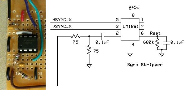
To process the NTSC video signal from the Xbox, first we need to strip the HSYNC and VSYNC pulses out of the signal. The HSYNC signal tells us when a new line is being drawn, and allows us to count down to the correct line for button detection. The VSYNC signal tells us when a new frame is started, allowing us to restart our line counting when the frame resets.
We decided to use the LM1881 Video Sync Stripper made by National Semiconductor. It comes in an 8 pin DIP and supports sync separation for NTSC, PAL, and SECAM video signals. The chip is able to run on the same 5V power supply as the MCU without any additional regulation. It outputs a Vertical Sync Output on pin 2 and a Burst/Back Porch Output signal on pin 5 that act similarly. They are both full swing 5V active low signals that go low whenever a VSYNC or HSYNC is active, respectively. The chip also outputs Odd/Even frame information that is not used in the project.
The HSYNC signal is outputted from the chip to one of the external interrupt pins on the MCU (PORTD.2 / INT0). The VSYNC signal is outputted from the chip to the other external interrupt pin (PORTD.3 / INT1). These interrupts will be used to count lines and frames in our software. The input from the chip comes from one output of the RCA splitter and is passed through a small 75Ω resistor and 0.1µF capacitor for coupling. On pin 6 of the chip there is a 1MΩ resistor and 0.1µF capacitor in parallel to ground to set internal current levels and decouple.
Video Low-Pass Filter:
Standard NTSC video is a color signal that carries both luminance (brightness) and chrominance (color) data over the same signal line. The chrominance data is encoded using two 3.579545 MHz signals. For this application we only need the brightness data to compare so we needed to strip the chrominance off of the input NTSC signal. We accomplished this by designing a low-pass filter with a cut-off bandwidth of 2.4 MHz. After some testing, we found that using a higher cut-off of 4.7 MHz gave us the best results. At this value, a lot of higher frequency noise is taken out of the signal, while some high spikes still remain to trigger our comparators.
Parts List:
| Component | Part # | Source | Cost | Qty. |
| Mega644 | Lab | $8.00 | 1 | |
| Custom PC Board | Lab | $4.00 | 1 | |
| Power Supply | Lab | $5.00 | 1 | |
| Solder Board (6 inch) | Lab | $2.50 | 2 | |
| RCA Y-Splitter | Radio Shack | $4.00 | 1 | |
| 10 Pin Flat Ribbon Cable | Lab | $0.00 | 1 | |
| Phototransistor Optocoupler | 4N35 | Lab | $0.00 | 6 |
| Video Sync Separator | LM1881 | National Semiconductor | $0.00 | 1 |
| RCA Plug | Lab | $0.00 | 1 | |
| Xbox 360 | Previously Owned | $0.00 | 1 | |
| Xbox Wired Guitar Controller | Previously Owned | $0.00 | 1 | |
| Color TV | Lab | $10.00 | 1 | |
| Header Plug | Lab | $0.05 | 12 |
Total Cost: $36.60
For more detail: Automated Rock Band player Using Atmega644