Our project was mainly designed for the Cornell Mars Rover project team (CMR), which will be using the robotic arm for competition to complete many different tasks in the deserts of Southern Utah.
For our ECE 4760 final project, we created the control systems for a robot arm that is able to use three different end attachments to perform a variety of specified actions, include pushing buttons, scooping up dirt or other items, picking things up with a hook, flicking switches, and taking voltage readings for solar panels. This robot arm uses the Arduino Mega2560 to take in commands from a user to determine which position to move to and what actions the arm needs to perform. It uses four different servo motors to control the four degrees of freedom over the wrist, elbow, and shoulder joints. Also, it controls three end attachments that are attached at the end of the arm: the hook, the scoop, and the control panel interface (CPI). Our controls are also able to open and close the scoop’s lid servo and turn on and off the brush of the CPI, which has two probes attached that takes the voltage readings.
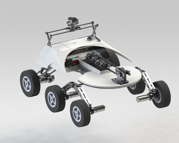
Table of Contents
High Level Design
Rationale and Sources
The leader of the CMR control systems team was seeking for recruits that can work on the robot arm to their rover. Because of our ECE background and our experience with PID and motors from lab 4, we decided that it was very appropriate to take on this task and that it would be perfect for our final project. The basic requirements and functionalities of the arm had already been set by the leaders prior to us joining the team, but we were constantly revising and changing the way some parts worked based on what we thought was most appropriate in implementing those requirements.
Background Math
The inverse kinematics and all the set torque and gear ratios were the tasks of other members on the Mars Rover team. We were in charge of mainly controlling the arm by using the PID mathematic feedback mechanism. The PID mechanism is a control loop that calculates the error between where the ‘variable’ is currently at and where it is supposed to be,its goal. It requires three correcting terms to calculate this error, the proportional gain, the integral gain, and the derivative gain. These three terms are summed together to calculate the PID’s output, as shown below in the two figures.
The hardware operates in a way that when you receive a serial input that tells the arduino to perform a certain task, the MCU would read the inputs and parse the commands, and then send it to the servo, which is connected to a potentiometer to determine its angular position. The servos are powered by an external DC power supply.
Figure: High Level Software Structure
There were three main functions that our software had to accomplish: run PID, get the serial inputs, and parse the commands. These all ran at different times, depending on whether it had reached the specified time to run the PID, if it received a serial input, and if a new command needed to be parsed after the goal was reached. It constantly ran these functionalities in a loop so that whenever the servos need to move to a new position, it would be able to do so.
Hardware & Software Tradeoffs
For hardware, we could have gotten cheaper servos that would be able to withhold the weight of the arm. However, because all the materials were funded by the project team, the extra torque was necessary so that we can make sure that no matter how much load needs to be picked up, the servos would hold. They were expensive, but they were also one of the better ones you will find out there. For software, we had the choice between coding in the Arduino IDE or C. Instead of programming in only one and not being able to experience the pros and cons of each one, we decided to do both and make a comparison between the two, in terms of their efficiencies and their execution speed.
Standards & Existing Patents and Trademarks
Our robot arm is closely related to a few available standards because it is implemented with serial communication and several motors. Serial communication is made between the main board, which sends the commands, and the Arduino, which receives and parses those commands. This follows the RS-232 communication standard. Also, the use of multiple motors follows the IEEE AC Motor Protection Standard because it allowed us to have all the necessary functions for adequate protection of our motors based on type, size, and application.
The robot arm is a common robotic component that is implemented in many different devices, and there are already many patents released. The very first idea of a robotic arm was patented in 1961 by George C. Devol, who engineered a mechanical arm that can perform simple tasks like lifting and grasping. Many other modern robotic arms with more joints and range of motions were designed based off of Devol’s innovation. However, what makes ours unique is its integration to the rest of the rover and the different functionalities that it has to be able to perform.
Hardware Design
For more detail: CMR Robot Arm