Introduction
This project implements a high speed data acquisition system using Mega32 microcontrollers and a Controller Area Network (CAN).
Recording data is essential to testing and developing a racecar. Recording what each sensor is doing can tell an engineering how the car is performing, and most importantly, how to make it faster. A well outfitted car can have many sensors, with Formula One cars having well over 100 sensors. Cornells FSAE car has over 50 sensors on it, many of which require high sampling rates to be useful. Commercial data acquisition systems are either expensive, slow, or have few inputs. A solution to this problem had been attempted by previous 476 students (Karl Antle and Ryan Mcdaniel) using a PIC18F2585, but it was only able to log reliably at 150 Hz. Many sensors on the car require much higher sampling rates, as the sensors are recording events occurring in a very short period of time. For example, when looking at a sharp bump using rocker position the event may only last .05 seconds when driving quickly. If taking the derivative of the data a very high sampling rate is required to give useful data, at least 500 Hz. It was this need for high speed data acquisition that motivated us to create a high speed data acquisition system to replace the current one.
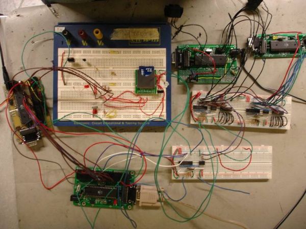
Our system uses multiple transmitter nodes to acquire data from sensors and transmit the data in packets over a CAN bus. Each transmitter consists of a Mega32 microcontroller, an external Analog-to-Digital converter, a CAN controller and a CAN transceiver. The CAN packets are received by a single receiver node and stored to a Secure Digital (SD) card. The receiver node consists of a 2 Mega32s, a CAN controller, a CAN transceiver, and a SD card. The goal of the project was to create a system which can record 32 10 bit ADC channels recorded by 4 Mega32s and transmitted over the CAN bus. In addition, the system should be expandable to accept CAN packets sent from other modules, such as an ECM or a standalone O2 unit. 500 Hz on the 32 AD channels was set as a goal for sampling frequency.
High-Level Design
The motivation for this project circled around the fact that high speed data acquisition using a single ATMEL or PIC is difficult when using many SPI interfaces. Controlling a SD card, 4 MCP3008 analog to digital chips and, if using a Mega32, a CAN transceiver on the SPI bus results in timing issues resulting in poor overall performance. The main issue results from the desire to sample at a regular rate. Writing to the SD card must be done in 512 byte sectors, which takes around 3.8 ms (found using a PIC18F2585 running at 40 MHz). If a regular sample rate is desired, there must always be 3.8ms in between sampling the AD chips so writing to the SD card does not disturb the regularity of sampling. Taking the AD sample time in to account, a maximum sampling frequency using one PIC or Mega32 processor is around 150-200 Hz (for the number of channels desired). For high performance systems, such as a racecar, 200 Hz is not enough for quickly moving sensors such as load cells and rocker position. To combat this problem, our data acquisition system uses many Mega32s working in parallel and series to avoid the SPI bus problems.
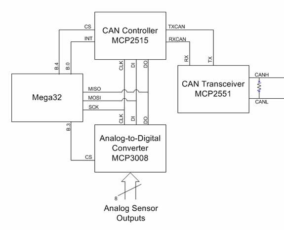
All main bottlenecks in the one chip system relate to the SPI bus. By separating the SPI bus functions among many chips, we eliminate that bottleneck in the system. As seen in Figure 1, our system uses one central unit which stores and receives data from four satellites over a CAN bus. The central unit consists of two Mega32s, one which receives the data from the satellites and one which writes the data to an SD card. The SD card is operating in SPI mode, as SD mode is a proprietary interface. The SD Mega32 communicates with the Receiver Mega32 through a parallel interface. The satellite processors handle reading the ADC chips, as well as putting the data on to the CAN bus. While these two SPI functions are controlled by the same chip, neither takes long enough to block each other when running at speeds under 2.5 kHz. As our target was much lower than this, it was deemed acceptable to use one chip controlling both SPI ancillaries.
Now that one bottleneck had been rectified, we had to ensure that the data transfer modes between chips were fast enough to meet the 500 Hz requirement. To ensure that we were going to have enough bandwidth to transmit the data through the CAN network, we calculated the number of bits required to send the data we needed to the receiving chip. To calculate this, the CAN standard must be understood.
The CAN 2.0b standard specifies the format of all packets and the encoding scheme used on the CAN bus. The CAN bus can assume one of two states, dominant (logical low) or recessive (logical high). If two devices attempt to drive the CAN bus simultaneously, one with a dominant bit and the other with a recessive bit, the bus will assume the dominant state. All devices read the value of the bus while transmitting. If a device transmits a recessive bit but reads a dominant bit, it knows that another device is transmitting and will wait until that device is finished to re-attempt its transmission. This system allows easy connection of multiple devices to the bus without any additional collision detection.
This system uses only Standard Data Frames (Figure 2). Each frame consists of a single dominant start bit, a 12-bit arbitration field used to establish message priority and identification, a 6-bit control field which includes the data length code, a data field ranging from 0 to 8 bytes, a 16-bit cyclic redundancy check (CRC) field for error detection, and a 7-bit end-of-frame field. In this standard, higher priority is given to frames with lower values of the arbitration field (dominant bits in the more significant positions).
Using this definition, it can be seen that only 64 data bits can be sent per packet. We will be recording 8 10-bit ADC channels in addition to 1 byte of identifier and 3 bytes of timestamp, for a total of 104 bits, or 14 bytes. To simplify the data decoding, we sent one 8 byte packet with the 1 byte identifier, 3 byte time stamp, and 4 bytes of data and one 6 byte packet with the remaining 6 bytes of data. Using the data frame depicted in Figure 2, it can be seen that since two packets are needed, 192 bits are sent total (Eq 1-3). As we would like to run 4 satellites at 500 Hz, the total data rate is 384kb/s (Eq 5).
Parts List:
| Part | Total Qty | Qty from Source | Source | Price |
| Custom PCB | 4 | 1 | ECE476 Lab | 5.00 |
| 2 | Borrowed from CU Minesweeper | free | ||
| 1 | Borrowed from FSAE | free | ||
| Mega32 | 4 | 1 | ECE476 Lab | 8.00 |
| 2 | Borrowed from CU Minesweeper | free | ||
| 1 | Borrowed from FSAE | free | ||
| DIP40 socket | 4 | 1 | ECE476 Lab | .50 |
| 2 | Borrowed from CU Minesweeper | free | ||
| 1 | Borrowed from FSAE | free | ||
| DIP20 socket | 4 | 4 | Borrowed from CU Minesweeper | free |
| MAX233CPP | 4 | 4 | Sampled | free |
| RS232 Conn. | 4 | 4 | Borrowed from CU Minesweeper | free |
| Whiteboard | 2 | 2 | ECE476 Lab | 12.00 |
| MCP2515 | 3 | 3 | Digikey | 8.94 |
| MCP3008 | 2 | 2 | Digikey | 5.80 |
| MCP2551 | 3 | 3 | Digikey | 4.35 |
| 16MHz crystal | 7 | 1 | ECE476 Lab | free |
| 6 | Borrowed from CU Minesweeper | free | ||
| 22pF cap | 6 | 4 | ECE476 Lab | free |
| 2 | Borrowed from CU Minesweeper | free | ||
| SD card slot | 1 | 1 | Borrowed from FSAE | free |
| SD card | 1 | 1 | Borrowed from FSAE | free |
| Power supply | 1 | 1 | Borrowed from FSAE | free |
| Power supply | 1 | 1 | Borrowed from CU Minesweeper | free |
| Header pins | lots | lots | Borrowed from CU Minesweeper | free |
| Total Price | 44.59 |
For more detail: Data Acquisition System With Controller Area Network and SD Card