Summary of Automotive On-Board Diagnostics Reader Using Atmega32
This article describes a handheld OBDII scanner built with an ATmega32 microcontroller to communicate with 1996–2007 Ford vehicles using PWM protocols. The device displays data on an LCD and sends it to a PC via RS-232 for logging. It features four communication routines, handles up to four simultaneous data requests, and strictly adheres to SAE J1850 standards for timing and error checking.
Parts used in the Automotive On-Board Diagnostics Reader:
- ATmega32 Microcontroller
- Moblie LCD Display
- RS-232 Serial Port Interface
- NPN Transistor
- PNP Transistor
- Comparator
- 10k Ohm Resistors
- Timer 1 Input Capture Function
- Ford Mustang (Test Vehicle)
Introduction
Our project is a hand-held device that is capable of communicating with any vehicle that uses pulse-width modulation (PWM) data-link layer. Such devices are commonly referred to as On-Board Diagnostic scanners. Vehicles that typically fall into this category are Fords made between 1996 and 2007. In our case, we used a 2003 Ford Mustang as the test vehicle for our device.
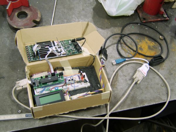
The diagnostic information can be displayed on our mobile LCD display with the option of sending the data to a PC running MATLAB for logging and plotting parameters like engine speed, oxygen sensor values, etc. This combines the convenience of a portable self-containted diagnostic tool with the added flexibility of a PC interface for advanced data acquisition.
back to top
High Level Design
Our device is designed to be a flexible, capable interface that allows the user to access every parameter that the vehicle’s system has to offer with little or no modification to the program. It is also designed to be expandable for future improvements like the addition of the (Variable Pulse Width Modulation) VPW, ISO 9141, and CAN protocols that are commonly used among other makes.
Four routines are responsible for most of the communication to both the vehicle and the PC. The first is the initialize routine that sets the microcontroller port, interrupts, and initializes the LCD and RS-232 port. The routine main controls the rest of the program. Currently, this program keeps a virtual timer and periodically calls the scanQueue routine. However, main could easily be expanded to use the PC to modify the requests made by the device to the vehicle as well as set other display or data acquisition options like one-time scans or continuously looped scans. While main could directly call the TxRxPWM routine, we wanted the functionality of monitoring several different parameters in tandem. To accomplish this, another routine named scanQueue cycles through up to four different data requests. Ultimately, the routine TxRxPWM is called to communicate with the vehicle. As one could imagine, additional functions like TxRxVPW or TxRxCAN could be created for communicating to vehicles of other protocols.
back to top
Program Design
The main routine of our program starts with an initialization which sets up all of the ports of the ATmega32 along with all of the program timers and interrupts. The LCD display is also setup during initialize, and a “starting” message is output for the user’s awareness. After initializing, main calls scanQueue which stores a series of requests for data that the user wants to monitor. These requests can range from current or past error codes, to vehicle speed, to ignition spark phase. The error codes are four digit numbers that correspond with a particular error in the vehicle’s system. An error is indicated when the “Check Engine” light is illuminated on the dashboard. Once the error code is read by our tool, the code can be referenced in a vehicle repair guide or in Society of Automotive Engineers (SAE) documentation, thus facilitating repair of the problem.
The scanQueue function can handle up to four different requests for information. Each call of scanQueue calls another function named TxRxPWM for each different request for information. It is TxRxPWM that handles all communication with the vehicle.
When TxRxPWM is called, it checks a character array that contains the information being requested from the vehicle. A request is specified by two bytes that are appended to a three byte header. For example, a request for engine speed would look like 0x416b10410c in which the first three bytes are the header and the last two bytes specify the parameter to be monitored—in this case, engine speed. From these five bytes, a sixth byte that is used for cyclical redundancy check (CRC) is calculated and appended onto the previous five bytes. The CRC is a more sophisticated parity check used to verify that the data was not corrupted during transmission. The algorithm for calculating the CRC byte is borrowed from www.obddiagnostics.com.
Before these six bytes are transmitted according to SAEj1850 PWM specifications, the vehicle’s bus is checked for activity. If the bus is active, then the transmission is delayed. If the bus is idle, then the six bytes are transmitted sequentially. Special symbols mark the beginning and end of a transmission. The start of frame symbol is a thirty-two microsecond dominant value followed by a sixteen microsecond recessive value. Each one of data is transmitted as an eight microsecond dominant value followed by a sixteen microsecond recessive, while each zero is transmitted as the opposite; sixteen microsecond dominant values followed by eight microsecond recessive values.
The data receive portion of TxRxPWM follows immediately after the transmission code. The reply from the car is captured using Timer 1’s input capture function. The bits are then decoded using the same timing scheme described for transmission and then placed into byte form. The data is then parsed via a search for special symbols, headers, and data. When a frame is sent to the car, the car replies with a series of frames of which only one or two are an answer to the request made. The code sifts through all of the vehicle’s responses until the reply sought is found. Finally, scanQueue displays the result on the LCD display and sends it to the PC via the RS-232 serial port. The interrupts that control the RS-232 port are courtesy of Bruce Land, instructor of Cornell’s ECE 476.
It is worth noting that we are working at the microsecond timescale and attention to timing is critical. For this reason, we disabled all interrupts during transmission, and only turned on interrupts when absolutely necessary. Interrupts were used during the receive routine as they were integral to proper functionality.
back to top
Hardware Design
The hardware provides an interface between the TTL logic levels of the microcontroller and the differential PWM bus that uses non-destructive arbitration. The vehicle’s bus is set up such that any one of multiple nodes on the bus can take control of the bus any time the bus is idle. Therefore, each node must monitor the bus to ensure that it is idle before broadcasting a message on the bus. If two nodes happen to begin broadcasting simultaneously, the node with higher priority (as specified by its header bytes) will remain in control of the bus while the node with the lower priority message will cease transmitting and wait until the bus is idle before trying again to broadcast to the bus. As specified in the SAE J1850 documentation, 0V on the positive bus is a dominant symbol while 5V on the negative bus is a dominant symbol.
The general idea for the circuit comes from www.obddiagnostics.com. To transmit on the bus, the MCU sends the PWM stream of data out on PORTD.5. Pin D.5 is jumped to pin D.7 which is configured as an input. This feedback ensures that the MCU always knows the state of the bus. The PWM signal is sent to an NPN transistor that pulls the negative side of the PWM bus low when the MCU outputs a high value. Otherwise, the bus is passively pulled high by a 10k ohm resistor. Simultaneously, the MCU output at D.5 is inverted with a comparator and sent to a PNP transistor that pulls the positive side of the PWM bus high. Similarly, the positive side of the bus is passively pulled low by a 10k ohm resistor. When the MCU outputs a low value, each bus is set in its passive state so that other nodes are free to use the bus.
To receive signals from the bus, each side of the bus is fed into a comparator via a 10k ohm resistor. The output connects to the MCU at pin D.6, which is the input capture pin for Timer 1. See Appendix B for the schematic.
Results of the Design
Our final project has met and exceeded our expectations from the begining of this course/project. The OBDII reader remained relatively compact and portable, and functions almost exactly as we first predicted. Our code conforms precisely to the SAEj1850 specifications, which provided a relatively easy process of working with Matt’s car. All interrupts were kept as simple as possible in order to allow the code to run as efficiently as possible.
Multiple tests have been run on our project with a few different test commands. RPM and engine temperatures have been read with extreme accuracy, and the reader itself appears to obtain correct responses from the car with over a 90% accuracy rate.
Our main safety concern on this project came from the fact that we were interfacing our project with Matt’s car. It is always necessary to be vigilant when working around running internal combustion engines in enclosed spaces due to the risk of asphyxiation. To avoid such risks, the project was always worked on outdoors, which alleviated such concerns.
Conclusions
In the end, we are extremely happy with the results we obtained. The OBDII reader successfully transmits and receives according to protocol from Matt’s Ford Mustang with very low data collision rates. Although we would have liked to have been able to implement VPW and/or CAN protocol, we are more than satisfied with a fully functional handheld PWM OBDII reader with LCD and PC readout.
Anyone looking to expand upon this project, or a future project for us might be to expand this reader to work on all cars with ECU access (not just those with PWM protocol). Another option might be to enlarge the library of built in requests to send to the car beyond those used in our project for proof of concept.
Our design conformed exactly to the SAEj1850 standards, with all communication protocols being designed with these standards in mind. Without strict conformity, the car would not respond to any of our device’s requests. The SAEj1850 standard is readily available from the SAE store or engineering library.
Our RS-232 code was taken from the ECE 476 website, and is the only instance of code being taken from the public domain. However, the CRC algorithm and the basic analog circuit were borrowed from www.obddiagnostics.com.
No reverse engineering was used at any time during the creation of our project, and no patent/trademark issues arose. Similarly, no non-disclosures were needed to be signed in the acquisition of any of our sample parts.

There are probably no patent opportunities as most of our hardware and software is already in existance in some form. Our project was more of a proof of conept using the ATmega32 than a new discovery.
By strictly following the protocol setup by SAEj1850 we adhered to all of the IEEE code of Ethics. In our report, all of our claims have been checked to make sure that they are both honest and realistic based on the observed data that we have physically seen and experienced. When possible, unaltered photos and graphs have been added to confirm the validity of our statements. Using our project as a proof of concept, using the Atmega32, we also believe that we have improved our understanding of current technology, and by way of the ECE 476 website will continue to improve the understanding of technology among future generations. In this way, we will assist our current and future colleagues in their professional development along with our own. In our quest to push the boundaries of what has been done with this technology we made sure to never undertake any tasks for which we are not qualified. Doing so ensured that safety was always taken into consideration, and that Matt’s car along with the property of the lab, all avoided injury. We also made certain that no part of our project interfered in any way with the projects of other colleagues in the lab, avoiding conflicts of interest and threats to the development of our colleague’s projects.
For more detail: Automotive On-Board Diagnostics Reader Using Atmega32
- Which vehicle models does this device support?
The device supports Fords made between 1996 and 2007 that use pulse-width modulation data-link layers. - How is diagnostic information displayed?
Data is shown on a mobile LCD display or sent to a PC running MATLAB for logging and plotting. - What is the maximum number of data requests the scanQueue function can handle?
The scanQueue function can handle up to four different requests for information simultaneously. - How is data integrity verified during transmission?
A sixth byte calculated via a cyclic redundancy check algorithm is appended to verify data was not corrupted. - What happens if the vehicle bus is active when transmission is attempted?
If the bus is active, the transmission is delayed until the bus becomes idle. - Why were interrupts disabled during transmission?
Interrupts were disabled during transmission because the project operates at a microsecond timescale where timing is critical. - What protocol standard does the design conform to?
The design conforms exactly to the SAE J1850 specifications.