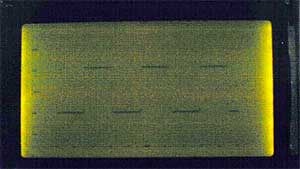
G1216B1N000 dot graphics display using AT90S2313 microcontroller

Download

I was looking for an LCD display that I could use to display waveforms on the workbench. The selection criteria for the display module itself was straight forward:
1. Dot graphic with sufficient resolution to display a simple waveform,
2. Available for fast delivery,
3. Have sufficient documentation available online to design with,
4. Be easy to interface to mechanically, electrically, and firmware wise, and
5. Have a low price.
The Seiko-Epson G1216B1N000 was selected, apparently meeting all criteria, but I was unable to get it to work until Jesper Hanse kindly sent me his driver for the driver for the display in his VAMPP4 TAMPP (Yet Another MP3 Player) and comparing his code with my code, I found some mistakes I had made.
dot graphics display

Connected to the a waveform capture unit, displaying a 15 kHz square wave.
I think the poor contrast has more to do with the digital camera’s low light
signal to noise ratio than the performance of the display.
The display is a pretty old transflective gray mode TN LCD design with ok, but not great contrast. Its contrast is better than the screen shot above. The display’s saving grace is that appeared to meet all of the primary criteria. The code to drive it was complicated somewhat by the fact that the 8 bit interface appears as two 64×64 displays for the left and right hand sides, and since I was determined to control it with an AT90S2313, I was a pin short of being able to have separate select pins for the left and right displays, and so implemented a Right/Left control pin, which produced some artifacts in the display, and avoiding these made it necessary to carefully code around them.
More about the hardware:
The controller was implemented with an AT90S2313, but it could have been done with an AT90S1200 and a firmware UART simulation since code is pretty small and doesn’t rely on the RAM or timers that an AT90S2313 provide. The hardware needs to drive the data and control lines of the Seiko-Epson module, supply an adjustable negative bias voltage and + 5 volts to the module, and provide inverting buffers for the RS-232 interface.
 
For more detail: G1216B1N000 dot graphics display using AT90S2313 microcontroller

About The Author

Ibrar Ayyub

I am an experienced technical writer holding a Master's degree in computer science from BZU Multan, Pakistan University. With a background spanning various industries, particularly in home automation and engineering, I have honed my skills in crafting clear and concise content. Proficient in leveraging infographics and diagrams, I strive to simplify complex concepts for readers. My strength lies in thorough research and presenting information in a structured and logical format.

Follow Us:
LinkedinTwitter

Leave a Comment

Your email address will not be published. Required fields are marked *

Scroll to Top