
Summary of LCD Date Time Application using AT89S52 microcontroller
This project implements a date-time alarm application using an Atmel AT89S52 8051-based microcontroller. Developed in C with Keil, simulated in Proteus (Isis and Ares), it provides timekeeping via Timer0 in mode 2, an alarm set with keys on port P0, LCD 2x16 display, LED indicator on P2.4, and supports automatic/manual reset. The system increments seconds/minutes/hours/day/month/year, handling month/day limits, and uses standard LCD control signals (D0–D7, RS, R/W, E, VSS, VDD, V0). External memory/EA pin behavior and power connections are also noted.
Parts used in the LCD Date Time Application using AT89S52 microcontroller:
- AT89S52 microcontroller
- 16x2 LCD module
- Timer0 internal to AT89S52 (mode 2 configuration)
- 3-key and 5-button input set connected to Port P0
- LED indicator connected to P2.4
- Pushbutton switch for alarm enable connected to P0_7
- +5V power supply
- Contrast potentiometer for LCD (V0)
- Data lines D0–D7 between microcontroller and LCD
- Control lines RS, R/W, E between microcontroller and LCD
- Proteus ISIS simulation environment
- Proteus ARES for PCB design
- Keil C compiler and development tools
This application can be installed at the same time an alarm indicating the date and time produced by Atmel with 8051 -based microcontroller AT89S52 tasarlanmıştır. Uygulamamızın using the Keil compiler using the C programming language using codes written in different types of intervention. Proteus simulation of the application program, Isis has been part of the program and the printed circuit board of Proteus Ares still drawn.
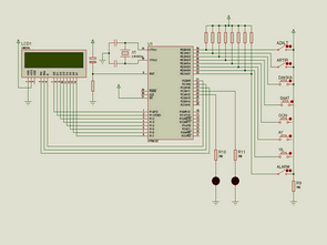
If we mention briefly the work of the application that is connected to port P0 mikrodenetleyicimizin 3-key and 5-button operation to be selected. For example, if the alarm is to be installed after the boost switch that is connected to P0_7’e Increase the key is to be switched off and the minute, hour by pressing the alarm buttons installed. The alarm was installed at the top of the circuit-sary and connected to P2_4 pin LED will light up. This allows the user to set the alarm circuit remote observing Sheddadis understand. Automatic and manual reset of the circuit are the two kinds.
Timer / sayıcı0 (T0), automatic loading (mode2) mode counting the value of 100 corresponds to the board-solidated and has every 10,000 count 1 sec. Later, a second increase control by traveling minute hour, day, month, and year values increased.
Year or month is changed automatically varies day. Changing these values are shown on the LCD 2 x 16 to the text. Than 10 s first line of the LCD text in a range of values.
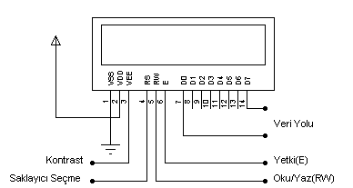
Text on the LCD can be seen in Figure 2 × 16. Today, LCDs are used in the standardized principles of operation and end connections. The LCD will read and write data from external data was delivered out of the data path between rebilmesini provides D0-D7.
The end of the number 1 to work on the LCD (VSS) and 2 end of frame (VDD) +5 volt supply voltage pin of the LCD image sharpness setting the number verilir.3 (contrast) is used for. In addition, register select (RS, Selected Register) end of the 8-bit data girişilerinden information, determines that it is a character code, or command. (RS = 0 data – RS = 1 command) Read / Write (R / W Read / Write) bit LCD to be used for data transfer or read data on the LCD. (R / W = 1, the data read operation R / W = 0, the process is carried out veriyazma.) Entitlement (E, Enable) bit operations for the realization of the desired logic level 1 established a single bit entry.
EA (External accsess): microcontroller (AT89S52) 31 The three terminal active low level. Or +5 volt supply voltage is connected to the chassis. +5 Volts is connected to the built-in software programs, external memory is connected to the chassis rum works.
For more detail: LCD Date Time Application using AT89S52 microcontroller
- How is timekeeping implemented in the application?
Timekeeping uses Timer0 in mode 2 with auto-reload; a count of 10,000 corresponds to 1 second. - Can the alarm be set using buttons?
Yes, the alarm is set using keys connected to Port P0 and the alarm enable switch on P0_7. - Does the LCD show date and time?
Yes, a 16x2 LCD displays the changing date and time values. - What indicates the alarm activation?
An LED connected to P2.4 lights up when the alarm is activated. - How are day and month limits handled?
The system automatically adjusts day values according to the current month and year. - Is there a reset option for the circuit?
Yes, the circuit supports both automatic and manual reset. - What tools were used to develop and simulate the project?
The project was developed in C using the Keil compiler and simulated in Proteus ISIS; PCB was drawn in Proteus ARES. - How does the LCD interface with the microcontroller?
The LCD uses data lines D0–D7 and control signals RS, R/W, and E for read/write and command/data selection.
