
Summary of G1216B1N000 dot graphics display using AT90S2313 microcontroller
The article details a project to display waveforms using a Seiko-Epson G1216B1N000 LCD driven by an AT90S2313 microcontroller. The author selected the display for its resolution, availability, documentation, ease of use, and low cost. Challenges included limited I/O pins on the microcontroller and the display's internal split architecture, which required specific coding to avoid artifacts. A negative bias voltage and inverting buffers were also necessary for the hardware setup.
Parts used in the Waveform Display Project:
- Seiko-Epson G1216B1N000 LCD module
- AT90S2313 microcontroller
- AT90S1200 microcontroller (mentioned as an alternative)
- Adjustable negative bias voltage supply
- +5 volts power supply
- Inverting buffers for RS-232 interface
- Waveform capture unit
Download
I was looking for an LCD display that I could use to display waveforms on the workbench. The selection criteria for the display module itself was straight forward:
1. Dot graphic with sufficient resolution to display a simple waveform,
2. Available for fast delivery,
3. Have sufficient documentation available online to design with,
4. Be easy to interface to mechanically, electrically, and firmware wise, and
5. Have a low price.
The Seiko-Epson G1216B1N000 was selected, apparently meeting all criteria, but I was unable to get it to work until Jesper Hanse kindly sent me his driver for the driver for the display in his VAMPP4 TAMPP (Yet Another MP3 Player) and comparing his code with my code, I found some mistakes I had made.
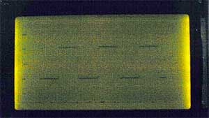
I think the poor contrast has more to do with the digital camera’s low light
signal to noise ratio than the performance of the display.
More about the hardware:
The controller was implemented with an AT90S2313, but it could have been done with an AT90S1200 and a firmware UART simulation since code is pretty small and doesn’t rely on the RAM or timers that an AT90S2313 provide. The hardware needs to drive the data and control lines of the Seiko-Epson module, supply an adjustable negative bias voltage and + 5 volts to the module, and provide inverting buffers for the RS-232 interface.
For more detail: G1216B1N000 dot graphics display using AT90S2313 microcontroller
-
Why was the Seiko-Epson G1216B1N000 selected?
It met all selection criteria including dot graphic resolution, fast delivery, available documentation, easy interfacing, and low price. -
What caused the initial failure to get the display working?
The author could not get it to work until comparing their code with Jesper Hanse's driver code and finding mistakes. -
How does the 8 bit interface appear internally?
The 8 bit interface appears as two separate 64x64 displays for the left and right hand sides. -
Why was a Right/Left control pin implemented?
It was implemented because the AT90S2313 had one pin short of being able to have separate select pins for the left and right displays. -
What is the nature of the display technology used?
The display is an old transflective gray mode TN LCD design with ok but not great contrast. -
Can the AT90S1200 be used instead of the AT90S2313?
Yes, it could have been done with an AT90S1200 and a firmware UART simulation since the code is small and does not rely on RAM or timers. -
What hardware functions are required besides the controller?
The hardware needs to drive data and control lines, supply adjustable negative bias voltage and +5 volts, and provide inverting buffers for the RS-232 interface.
