Runners who have moved to a new city may get lost trying to remember the route they carefully planned at home. Instead of stopping the run to pull out a phone, wait for the map to load, find where you are, and determine where you need to go, why not carry something that will automatically tell you where to go without interfering with your run? The GPS Running Watch is a personal GPS guidance device to help runners follow unfamiliar routes using an LCD display and haptic feedback. It guides the user along a path between preselected latitude/longitude waypoints by vibrating a small motor to indicate whether the waypoint is straight ahead, to the left, or to the right. You can stop worrying about losing your way home, and get back to enjoying your run.

High Level Design
Rationale
The idea for this project came from a brainstorm of different applications for GPS. GPS receivers are everywhere in the modern world, and are small and simple enough to use with a microcontroller to a reasonable degree of accuracy. There are many websites and smartphone apps that can help runners find and create routes but what they don’t do is guide runners while running those routes. There is no feedback to indicate where the next turn is, or in which direction to turn. A smartphone app could interrupt music that may be playing to indicate when and how to turn, but that would remove the user from the general peace of the run and force the user to think about the next turn. All those interruptions could get very irritating. A better solution would be to indicate the next turn through haptic feedback. A vibration on a user’s left arm would naturally indicate a turn to the left, and a vibration on the right arm would naturally indicate a turn to the right. We use this method of feedback to seamlessly guide the user along a route without interrupting the run.
Logical Structure
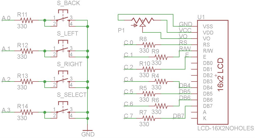
Our device provides basic route navigation guidance and waypoint logging using GPS. An ATMega1284 microcontroller unit (MCU) receives GPS data from a receiver module, and user selections from four pushbuttons. The pushbuttons allow the user to move through different menus, make selections, and return to previous menus or exit the current function. During route navigation, the MCU displays route information on an LCD display and gives turn indications through two vibration motors. The MCU retrieves waypoints from routes saved in text files on an SD card. For waypoint logging, the MCU only uses the LCD display and not the vibration motors. The MCU saves waypoints to a text file on the SD card.
The GPS module sends NMEA strings containing certain GPS data over a serial communication line. The MCU can control the speed of the data connection, the update rate, and the type of information that the module provides. We chose a 9600 baud rate with a 1 Hz update rate for new information, which is fast enough for our application. The GPS module provides the GPGGA and GPRMC NMEA sentences to the MCU. These sentences give the receiver’s latitude, longitude, altitude, speed, and bearing, the current UTC time, and the state of the GPS satellite fix. We use all this information for the route navigation function, and all except the speed and bearing for the waypoint logging function.
The SD card stores routes as a list of comma-separated latitude/longitude waypoints in text files. The first line in these text files is a header with no useful information to the MCU. Each subsequent line contains a waypoint starting with a ‘T’ followed by a latitude, a longitude, a waypoint name (not necessary), and a description (also not necessary). As mentioned before, each of these five values are separated by commas to make it easy for the MCU to parse them. The MCU only extracts the latitude and longitude from each line and stores them in two arrays: one for latitudes, and one for longitudes. It moves through these arrays as the user runs the route. In the waypoint logging function, the MCU stores waypoints in the exact same format. We use this format because it is used by the website we use to convert between text files and Google Earth KML files (www.gpsvisualizer.com).
The GPS Visualizer website makes it much easier to use Google Earth to create and view routes. While a user could create a text file with our format by entering each latitude and longitude, a less tedious solution, which we recommend, is the following:
- Create a path in Google Earth
- Save the path as a KMZ file
- Upload the KMZ file to the GPS Visualizer website and output a comma-separated text file
- Copy the output to a text file and save this text file to the SD card
A user can view his saved waypoints from the waypoint logging function in a similar manner:
- Upload the text file to the GPS Visualizer website and output a KML file
- Use Google Earth to open the KML file
- The path should appear as a series of red lines as shown below
The LCD displays certain information to the user depending on the current function. In route navigation, it displays the current waypoint number, the elapsed time since the start of the run, the distance in meters to the next waypoint, and the runner’s current speed in kilometers per hour. When the user completes the run, it displays the total completed distance of the run and the total time. During waypoint logging, the LCD displays the current local time, and the user’s latitude, longitude, and altitude. Outside of these two functions, it displays different menus.
Hardware and Software Tradeoffs
Hardware
There were four major hardware tradeoffs in this project: wired vs. wireless communication, board size, battery size, and LCD type. Since our hardware is split into three groups situated on three different parts of the user’s body, there has to be some way for all the hardware to communicate. The simplest solution is to run wires between the different groups. Wires and pin headers are cheap, relatively compact, and do not require additional software. On the other hand, wires can restrict the user’s movement, which is not ideal for runners. Another solution is to use short-range wireless RF communication, such as Bluetooth. Bluetooth would not restrict the user’s movement. However, it can be difficult to use with microcontrollers, requires more hardware and software to run, adds more weight than wires, and is significantly more expensive than wires. Considering our time and budget constraints, we chose to use wires even though wires impede the user experience to some degree.
The main board in our project is much bigger than it could be because we are using a PDIP-package ATMega1284. If we had designed our own printed circuit board (PCB) and used a TQFP-package ATMega1284, the main microcontroller board could be half its current size (just the size of the green PCB in the picture). A smaller board would be better for the user who has to wear it on his arm, and could better incorporate the battery pack. Although a PCB has benefits, it is also more expensive, more time-consuming in design work and fabrication, and harder to fix if we made an error in the design. Since time and budget are our two main constraints and we already had a microcontroller carrier board from the lab, we decided to use the carrier board and a protoboard to connect the other hardware.
Our choice to use 3 AA batteries to power the project was a little unintended. Since one of us already had a battery holder for 3 AA batteries, it was a quick and easy solution for powering the hardware for outside tests. The voltage from the AA batteries starts around 4.7V and drops to around 4.5V over time, which is still acceptable for 5V devices, and doesn’t require a voltage regulator. The ATMega1284 will run at 16 MHz with at least 4.5V, so the AA batteries work. A better solution may have been to use a two-cell lithium battery with a small voltage regulator. A lithium battery would have been much smaller and lighter than the AA batteries, and could have been recharged with an on-board recharging circuit. Since the AA batteries worked just fine and were readily available, we forgot to consider lithium batteries any further. In retrospect, lithium batteries would have been better for weight and size, but they have more safety problems and require more on-board hardware for charging or an external charger. A compromise on size and weight may have been to use AAA batteries instead of AA batteries, but we did not consider this change worthwhile as we already had a AA battery holder.
The last hardware tradeoff was the LCD. The LCD is the main visual interface, and the only user interface during the waypoint-logging function. A larger character LCD would allow us to display more information to the user, but would also be bulkier and heavier. Since the LCD is sitting on the user’s forearm, the size and weight should be as small as possible to reduce fatigue. A 16×2 character LCD, like the one we use, is a good tradeoff for these criteria. However, a graphic LCD might be able to display more information, albeit in a smaller font, with a smaller board size. We chose to not use this type of display because it is often more expensive, requires more software, and would display information in a smaller size, which would not be ideal for some users.
Software
The main software tradeoff was whether or not a real-time kernel would be used. A real-time kernel has the advantage of easy timing of multiple tasks that need to be run simultaneously. A custom scheduler on the other hand allows for more precise timing of time-sensitive tasks and the ability to ensure the MCU is never overloaded. Because the project does not require many simultaneous processes, a real-time kernel is not required. Additionally, two tasks, including the clock for the SD card, and the GPS update signal needed to be called at certain intervals. Therefore, a custom scheduler was used that was run off of TIMER0 with a 1ms time-base.
Parts List:
| Item | Vendor | Part Number | Unit Cost | Quantity | Total Cost |
|---|---|---|---|---|---|
| Adafruit Ultimate GPS V3 | Adafruit | 746 | 39.95 | 1 | 39.95 |
| Vibration Motor | Adafruit | 1201 | 1.95 | 2 | 3.90 |
| AA Battery | Wegmans | – | 0.66 | 3 | 2.00 |
| Velcro Strips | Lowes | 319808 | 19.97 (30ft) | 3 ft | 2.00 |
| SD Card Holder | Cornell Lab | – | 0.00 | 1 | 0.00 |
| 128MB SD Card | Cornell Lab | – | 0.00 | 1 | 0.00 |
| 16×2 Character LCD | Student | – | 8.00 | 1 | 8.00 |
| Pushbutton | Cornell Lab | – | 0.00 | 4 | 0.00 |
| 2″ Solder Board | Cornell Lab | – | 1.00 | 1 | 1.00 |
| 6″ Solder Board | Cornell Lab | – | 2.50 | 1 | 2.50 |
| ATMega1284 | Cornell Lab | – | 5.00 | 1 | 5.00 |
| Custom PC Board | Cornell Lab | – | 4.00 | 1 | 4.00 |
| 2N3904 Transistor | Cornell Lab | – | 0.00 | 2 | 0.00 |
| 1N4001 Diode | Cornell Lab | – | 0.00 | 2 | 0.00 |
| Potentiometer | Cornell Lab | – | 0.00 | 1 | 0.00 |
| Various Resistors | Cornell Lab | – | 0.00 | 14 | 0.00 |
| Switch | Cornell Lab | – | 0.00 | 1 | 0.00 |
| Header Socket | Cornell Lab | – | 0.05/pin | 98 | 4.90 |
| Header Pin | Cornell Lab | – | 0.05/pin | 19 | 0.95 |
| Battery Holder | Student | – | 0.00 | 1 | 0.00 |
| Total | 74.20 |
For more detail: GPS Running Watch Using Atmega1284