Summary of How to fix dead atmega and attiny avr chips
This project describes the Atmega Fusebit Doctor, a device designed to repair "dead" Atmega and Attiny AVR microcontrollers by restoring their fusebits using high-voltage parallel and serial programming. It addresses common issues like wrong clock source, disabled SPI programming, or disabled reset pin that standard programmers cannot fix. The device supports multiple AVR packages via dedicated sockets and adapters, features LED indicators for status, and can optionally erase chip memory to enable fusebit repair. The programming method is based on AVR datasheet guidelines to restore factory fusebit settings, reviving otherwise non-functional AVR chips quickly and affordably.
Parts used in the Atmega Fusebit Doctor:
- DIP28 socket (compatible with Atmega8)
- DIP20 socket (compatible with Attiny2313)
- DIP40 socket (compatible with Atmega32)
- Goldpin connector for adapters
- HVPP adapter (for DIP20-B Attiny26 and DIP40-B Atmega8515)
- HVSP adapter (for DIP8 Attiny13 and DIP14 Attiny24)
- START push button
- Green LED (status indicator)
- Red LED (error indicator)
- ALLOW ERASE jumper
- USART interface for data communication
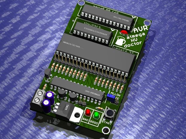
Atmega fusebit doctor, as name says it, device for repairing dead Atmega and Attiny family AVRs by writing fabric fusebits. Most common mistakes or problems are a wrong clock source (CKSEL fusebits), disabled SPI programming (SPIEN fuse) or disabled reset pin (RSTDISBL fuse). This simple and cheap circuit will fix you uC in a fraction of a second.
If in first case we can help ourself with clock generator, then in 2nd and 3rd cases bring uC back to life is impossible with standard serial programmer. Most of people do not decide to build parallel programmer because its inconvenient and its cheaper and faster to buy new uC.
Step 1: Sockets
This circuit use the high-voltage parallel and serial programming method. Atmega8(doctor) has saved in it’s memory signatures of 96 (so far) AVR Atmega and Attiny uC’s, just put your dead avr in socket, press the START button, and enjoy your good-as-new processor.
There are three slots on board, for most common AVR’s, pins compatible with: DIP28 Atmega8, DIP20 Attiny2313, and DIP40 Atmega32 compatible processors.
There is also an extra goldpin connector with all signals so you can attach adapters:
-the “#1 HVPP adapter” with DIP20-B Attiny26 and DIP40-B Atmega8515 compatible
-the “HVSP adapter” for tiny DIP8 Attiny13 and DIP14 Attiny24 compatible.
-your own adapters for other types of processors, in trough-hole or surface-mounted, you can use the breadboard for this – just connect signals to correct pins. How? Check your AVR datasheet, go to “memory programming” and then “parallel programming” – check the signal names, all signals are described under the DIP40 slot.
Step 2: Montage note
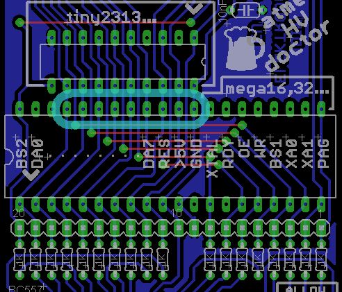
ATTENTION! While mounting the DIP40 slot, you must to remove it pins from 29 to 37. These pins must not have electrical contact with inserted uC pins. Take a look at this pic, these you must remove from slot:
Step 3: Other
Leds explanation:
green on – patient successfully cured, fusebits repaired. If lockbits are enabled, just verify fusebits with factory ones – and if they ok – light up green.
red on – signature problem, can’t read, no device in socket, or no such signature in database.
green flashing – signature ok, fusebits are wrong. Lockbits enabled, chip erase permission required (read below).
red flashing – signature ok, no lockbits, but for some reason can’t write new fusebits.
The ALLOW ERASE jumper allows doctor to erase whole flash and eeprom memory, if it is open, doctor will newer erase memory but may not cure device if lockbits are enabled, so you choose. After insert dead uC and press the START button, doctor will initiate the parallel programming mode. If our patient will not respond with high state at RDY/BSY line, doctor will use other way to initiate programming mode even if the XTAL pins are switched to external resonator. After that doctor will erase whole memory if user allows that. Then, read device signature and check if it supports it. Next are lockbits checked, and if they not blocking device, doctor sets all fusebits to fabric, having regard to whether there are extended fusebits or not. After that fusebits are verified, and proper leds are flashed. Also, all the info are send trough usart.
Code was written based on high-voltage parallel programming section of datasheet of suitable AVRs.
Fusebits: Internal 8MHz clock, and enabled EESAVE bit.
For more detail: How to fix dead atmega and attiny avr chips