Introduction
Single sentence summary
A programmable laser light show that allows the user to specify the pattern displayed via three motor speeds and the length of time that this pattern is held.
Project Summary
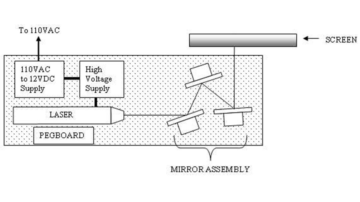
For this project, we designed a system to guide a laser beam through an array of three rotating mirrors and then project it onto a screen where it is able to “draw” a range of different patterns. Allowing the mirrors to rotate at variable speeds creates the different patterns. These variable speeds of the motors are produced via pulse width modulation (PWM) control from the MCU. Each motor has its own dedicated pulse width modulator, allowing each motor to rotate at a different speed.
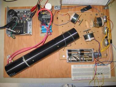
Our project can be broken down into a few major constituent components. These components include the laser tube and high voltage power supply, the mirror assembly (three circular mirrors and motors), the Atmega32(L) (and STK-500), and finally a custom made board which contains the PWM support circuitry. All of these components are mounted on a piece of pegboard making the unit easily portable. Additionally, a user interface for the motors has been implemented that uses HyperTerminal. Each one of these components is discussed in detail below.
We decided on this project after discussing the types of potential projects we could complete and jointly decided that since we never dealt with any type of motor control in lab that the final project was a good opportunity to do so. Additionally, after a trip last summer to Darien Lake amusement park where we watched a professional laser light show, we both had wondered how exactly this type of presentation was done. After a bit of research, we concluded that for the time allotted for this project, this tri-mirror setup was the most feasible.

High level design
Rationale and sources of your project idea
To develop the idea of this project, we first built the system using hardware only. The system was the same as in the final design with the exception that all motor control was done with potentiometers instead of PWM control. This allowed us to experiments with different numbers of mirrors, different ranges of speeds and different arrangements of the mirrors themselves. From this experimentation, we were able to make many decisions regarding the way the final project should be constructed.
Firstly, we decided on three motors/mirrors for a number of different reasons, the main reason being that we could maximize the number of patterns available for display by maximizing the number of mirrors. The Atmega32(L) contains four pulse width modulators from three timer sources. One of these timers must be dedicated to program control, this leaves a maximum of three PWM channels from a single chip. Hence, we decided that three mirrors and motors was the proper choice.
For more detail: Laser Light Show

