Spice up your poker games with these cool blinking chips. They can be programmed on the fly to have a certain number of the LEDs illuminated to indicate value, or you can have the lights blink in a cool pattern. They make great playing chips for championships or great prizes to hand out to the winners. Let’s get started!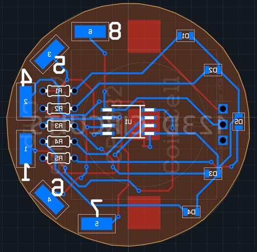
In order to get this circuit as small as it is you’ll need to order the printed circuit board I designed. You can breadboard it, but this would defeat the purpose; the whole point is that the design is the size of a poker chip. Here’s the order link for OSH park: https://oshpark.com/shared_projects/RmkVGeN9.
Step 2: About the Board
This printed circuit board has a few tricks up its sleeve. The brains of the operation is an SOIC-8 ATtiny85. In order to program the ATtiny, six pads are needed to connect to an Arduino Uno. I’ll discuss this a bit more later, but you can connect to these with alligator clips. A 3V CR2032 provides more than enough power for the entire circuit. No voltage converters are needed; the ATtiny is more than happy to run off of the battery as-is.
Step 3: Soldering the “Hard Stuff”
This circuit is a great introduction to surface-mount soldering if you’ve never done it before. I would definitely say that the hardest part about the project is correctly soldering the small 0805 LEDs. The first step to soldering them is determining their polarity, as LEDs are polarized components. I used the following link to do this: http://www.limetrace.co.uk/how-to-determine-the-polarity-of-an-smd-led.
LEDs
You can then start soldering the LEDs. I watched this video to help me do this with a soldering iron:
For all of the horizontally-oriented LEDs, the positive side of the pads is pointed towards the rest of the board, not towards the outside. For the vertically-oriented LED the positive pad is pointing downwards, or closest to the label “7.” When I’m done soldering SMD LEDs soldering I always like to do a continuity check with my multimeter to see if both pads are making good contact. For the ground of the LED you can touch the other probe of your meter to the pad labelled “4.” For the positive side of the LED you can touch your other probe to all the pins on the ATtiny and see if one of them makes contact with the LED you’re testing.
Step 4: Soldering the “Easier Stuff”
The rest of the components that you need to solder should be very easy. In comparison to the LEDs, soldering the SOIC ATtiny85 is a piece of cake. Just make sure that the dot on the chip is closer to the LEDs and not the resistors.
I made a little mistake on the battery connector’s silkscreen. The arrow that indicates which way the battery should slide in is facing in the wrong direction. When soldering the battery connector, make sure that the switch doesn’t block you from being able to slide in the battery. I also like to put a small bit of solder on the ground pad to make sure the battery makes proper contact with it.
The remaining resistors and slide switch are regular non-polarized through-hole components. Solder them as you would any normal component.
Step 5: The Sketch
Included in the attachments section of this build is a demo sketch that displays the capabilities of the Light-Up Poker Chip. If you let it sit for 10 seconds without doing anything a demo of lights flashing around the outside will start. You can also set the state of the lights on the chip to be on or off without needing to re-upload software to the chip. To see how to do this, watch the video I linked at the beginning of the story section of this build.
Step 6: Programming (i.e. a mess of alligator clips)
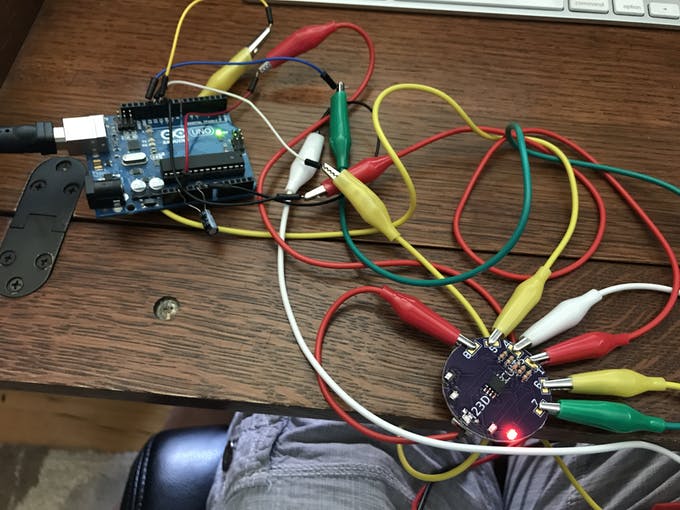
he pads that line the exterior of the board are used for programming purposes. I could have used regular female or male headers, but I wanted to keep the whole package as low-profile as possible. This tutorial shows you how to program the chip: https://create.arduino.cc/projecthub/arjun/programming-attiny85-with-arduino-uno-afb829. The pads are labelled with the pin number of the ATtiny (8 is VCC, 4 is ground, 1 is reset, etc). Use alligator clips to connect the male jumper wires from the Arduino Uno to the pads.
For more detail: Light-Up Poker Chip