This is basically a knockoff of the Hypnocube, instead of being 64 LEDs, thus costing at least $150 to make, I made a smaller version of 8 LEDs for under $30.
The result is a 2x2x2 cube where each light is independently controllable. I’m not absolutely sure how many colors you can get from each light, but I could do 64 nicely without any “vibrations” in the color.
http://www.hypnocube.com
Step: 1 Materials
Yes, you actually have to build with stuff. Since its so new to you, I’ve outlined everything you might need.
*Hardware
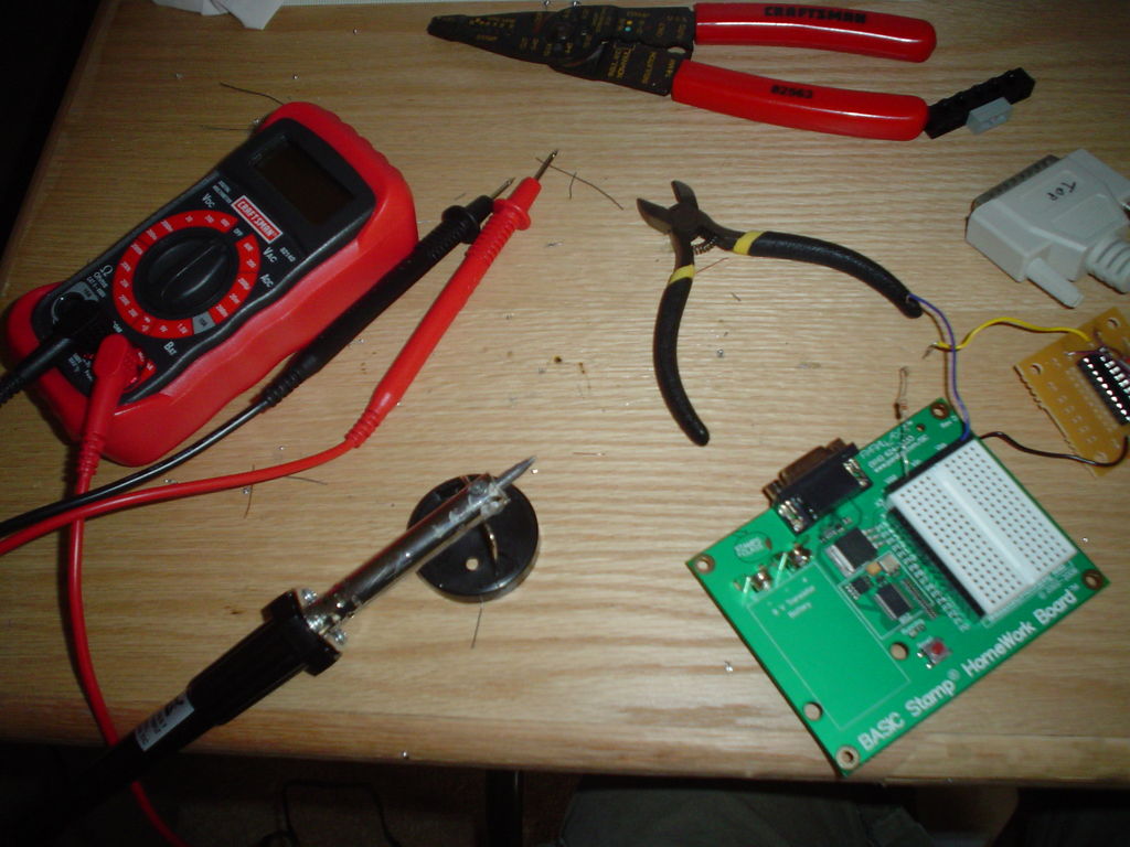
*Soldering Iron (Fine tip is needed)
*Solder
*Wire Cutters/Strippers
*Legos (The Technic kind that have the holes along the side)
*AVR Programmer (See Below)
*Continuity tester
*Parts
*8 RGB LEDs
*1 Atiny2313
*Resistors
*Wire
*Stiff Wire (Plastic twist-ties)
*Way to provide 5v (Wall wort, batteries, regulator, etc)
*Optional
*Protoboard/PCB
*Breadboard
*White Translucent Paint
*Programmer
*Parallel Port (Male, 20 Pin)
*20-Pin DIP Socket
*Protoboard or 20 Pin DIP Breakout Board
Yes, you DO need the Legos. They are the perfect jig for this project. If you cannot procure them, you will have to make a jig out of a 2×4.
I made an AVR programmer very similar to the one mentioned in the Ghetto Programming instructable, except I left out the header pins and soldered the wires directly to the pin’s traces. Visit his instructable to figure it out, and get it working with your computer.
In some of my pictures you may see a Basic Stamp board, but I am just using it for it’s 5v power supply, and its breadboard.
I bought all my parts at SparkFun Electronics, and I was very pleased.
Step: 2 Planning
Since I’ve already done this for you, you don’t actually have to do this step! These are just some preliminary thoughts that went into it.
Since my RGB LEDs were not frosted, and the colors were “separate”, I decided to paint them with an acrylic paint that is used normally for a matte finish. I thinned it down with another paint that was transparent when dry, and had a small gloss to it. The result was quite pleasing, as you can see with the first few pictures.
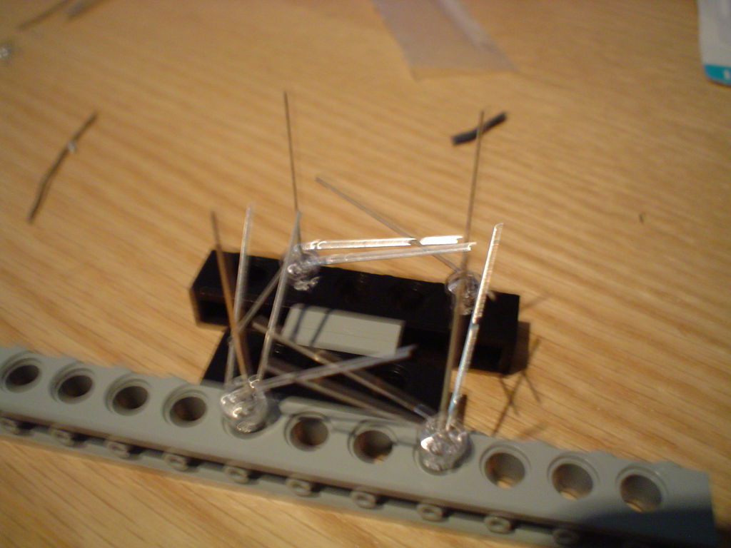
Before embarking on building this, I made a prototype of it using regular LEDs that I had lying around. As you can see in the second “group” of photos. The first is 4 LEDs in my Lego Jig. Basically, you need it to be six studs long, and 3 bricks and 2 plates high, and its incredibly close to being square. (Its 0.07 studs off, for you number freaks)
I bent the anodes (the shorter ones) over and then soldered them to the next bent-over anode. You cannot touch the cathode! If you try soldering this and think its hard, its just getting started! Once thats done, repeat with the next set of LEDs.
Then, bend the ends of the cathode pins inward slightly, as in picture #6. Solder these to the bottom set of cathodes, without touching the anode “ring”.
Finally, get 2 pieces of stiff wire, and solder connections from each anode ring to the bottom, for a total of 6 connections from the bottom.
The LEDs are now multiplexed. Select the tier and column to light up an LED. It worked, and I was ready to move on to the real thing.
Excuse my Marco-mode-less-camera. I’ll try to explain the unseen detail using Photonotes. (They should be 3.1 megapixel images, so if you do decide to make it, maybe you can zoom it on it)
Step: 3 The Good
In keeping with the Hypnocube’s instructions, I’ve made 3 sections with the same name: The Good, the Bad, and of course, The Ugly.
You may think that these are fun little monikers, but seriously. While it will take you a minute to read The Ugly, it took me 2 hours to do for the first time.
You can start off by seeing how you’re going to bend the LEDs. Mine went RCBG, yours may be different, so check!
Next, place all 4 LEDs into your jig. such that the leads are pointing diagonally inwards, red in the closest, the cathode. When you bend the red’s, they should just touch, if not go a bit over the last red. Then fold the blues in the opposite direction, then the greens in the same way as the red. The blues should almost reach, maybe like 1mm off, but the greens will be over 1cm too short.
At this point, I bent the cathode slightly away from the reds, to give me some soldering room, then soldered all the reds together. After you get that red ring done, you should test for continuity across the ring. If you got close to the cathode, do a test for continuity to make sure you didn’t solder to it. If you did… well try to get it out.
That was the easiest step! YAY!
Step: 4 The Bad
So, now that you’ve soldered red, its time to move onto green and blue.
Carefully position the blue lead as close as you can get it to the next one. It will probably have a 1mm gap. Luckily, solder is good at that.
(Warning! If you have the iron too hot, you may bridge the gap, let go, and the lead will spring back, throwing hot solder all over you!)
On red, you wanted to use as little solder as possible. Here, I used a larger glob. Don’t use too much, or you will solder to another wire.
(If you do, check out step 5.)
Repeat 4 times, and now you’ve got a blue ring! Yay! Make sure to check for continuity 😉
The Bad wasn’t really that bad, was it?
For more detail: Mini RGB Light Cube using AVR microcontroller


