
Summary of Control Anything with one AVR pin using Attiny2313 microcontroller
This article details a project using an Attiny2313 microcontroller to control multiple LEDs via a single output pin through low-side switching. The setup utilizes transistors or MOSFETs as switches, powered by a 5V regulator and an external power source like a laptop charger. It explains calculating resistor values based on LED voltage drops and Ohm's Law to manage current flow efficiently in series-parallel arrays.
Parts used in the LED Control Project:
- Attiny2313 microcontroller
- 20 pin socket
- Resistors
- 5v regulator (LM340)
- NPN Transistors (2n3904) or N-Channel Mosfets
- Capacitors (.1uf and .22uf)
- LEDs
- Protoboard or breadboard
- AVR programmer
- Wire
This instructable shows how to control a group of led’s with one microprocessor output.
The micro I will be using is an Atmel Attiny2313.
Step: 1 Parts and Tools

Parts:
Attiny2313 (got 5 free samples from Atmel)
20 pin socket
Resistors (any size will work, depending on your setup. I will explain later)
5v regulator (any will work, I’m using an LM340)
Transistors or Mosfets (easiest to find and cheapest ones are usually 2n3904’s. Just make sure it’s an NPN transistor, or an N-Channel Mosfet)
2 small Capacitors (look up data sheet for regulator, .1uf and .22uf with LM340)
Lots of LED’s
Some protoboard or a breadboard
Any programmer for the AVR
Wire
Tools:
Soldering Iron
Step: 2 Schematic and How it works
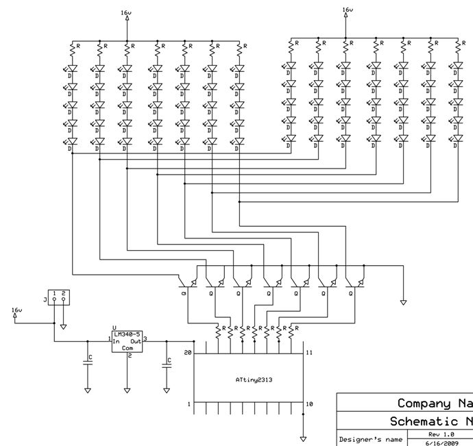
The first schematic shows how I hooked up rows of led’s to output pins. The output pin of the AVR goes to the base of a transistor, which is wired to work as a switch. When the output is low, or 0v, the transistor is off, and the current can’t flow through the load to ground. When the output is high, or 5v, the transistor is on and current can flow through the load to ground. This is called low side switching, and can be used for led’s, dc motors, stepper motors, and many other things that require more voltage or current than the micro can output.
The load for this project will be some led’s.
The led’s can be wired any way that you want, but the power supply you are using will determine how you can hook them up.
For me, I found a laptop charger which can output 16v at 7.5 amps max.
Now the most efficient way to hook up the leds was in a series parallel array as shown in the third picture.
To determine the resistor size, first find out how much voltage is dropped per led. For blue and green led’s that I used, the voltage drop is around 3 to 3.3 volts. Red and yellow led’s are around 2.2 volts.
Now add up all of the voltage drops in series (3*5=15v)
Now subtract that from your source voltage (16-15=1v)
Now you know how much voltage is dropped by your resistor (1v)
Now use ohm’s law to solve for R: V=IR (1v=.015R)
*I used 15ma for my led’s, this is typical for 5mm led’s
So now each strand is using 15ma from your supply.
Each strand can be its own load, or you can attach as many together as you want, as long as the total current for that load does not exceed the limit for the transistor. (2n3904 can handle 100ma)
*The transistor can be replaced with an N-Channel Mosfet
For more detail: Control Anything with one AVR pin using Attiny2313 microcontroller
-
How does the transistor function in this circuit?
The transistor acts as a switch controlled by the AVR output pin; it turns off at 0v and allows current to flow when the output is high at 5v. -
What type of switching method is described?
The project uses low side switching where current flows through the load to ground when the transistor is activated. -
How do you determine the correct resistor size for the LEDs?
You calculate the total voltage drop of the series LEDs, subtract it from the source voltage, and use Ohms law with the desired current to solve for resistance. -
What is the maximum current handling capacity of the 2n3904 transistor?
The 2n3904 transistor can handle up to 100ma of current. -
Can I replace the transistor with another component?
Yes, the transistor can be replaced with an N-Channel Mosfet for this application. -
What voltage drop should I expect for blue and green LEDs?
Blue and green LEDs typically have a voltage drop around 3 to 3.3 volts. -
Is there a specific limit on how many LED strands can be connected?
You can attach as many strands together as long as the total current does not exceed the limit for the specific transistor being used.
