RFID technology brought a great revolution in our life as it simplifies the machine communication. RFID’s are used almost everywhere today Schools, hospitals, industries and much more. This article teaches you to build a simple RFID based security system using AVR microcontroller which is reliable and cost efficient. You gotta be familiar with working principle and interfacing RFID so kindly go through this ” How to interface RFID with AVR Microcontroller ” tutorial before proceeding with this project.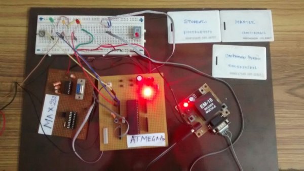
This system uses a RFID reader module and RFID tags which uses serial communication UART for communication. This RFID module senses the 12 bit ID of the tag once it is brought within the range. The unique ID is then sent to the Microcontroller for further processing via UART protocol. Since the module operates at RS232 logic +25V to -25V , we need to use level converter IC MAX232 to convert the data to TTL logic for Microcontrollers.
DESIGN OF RFID BASED SECURITY SYSTEM:
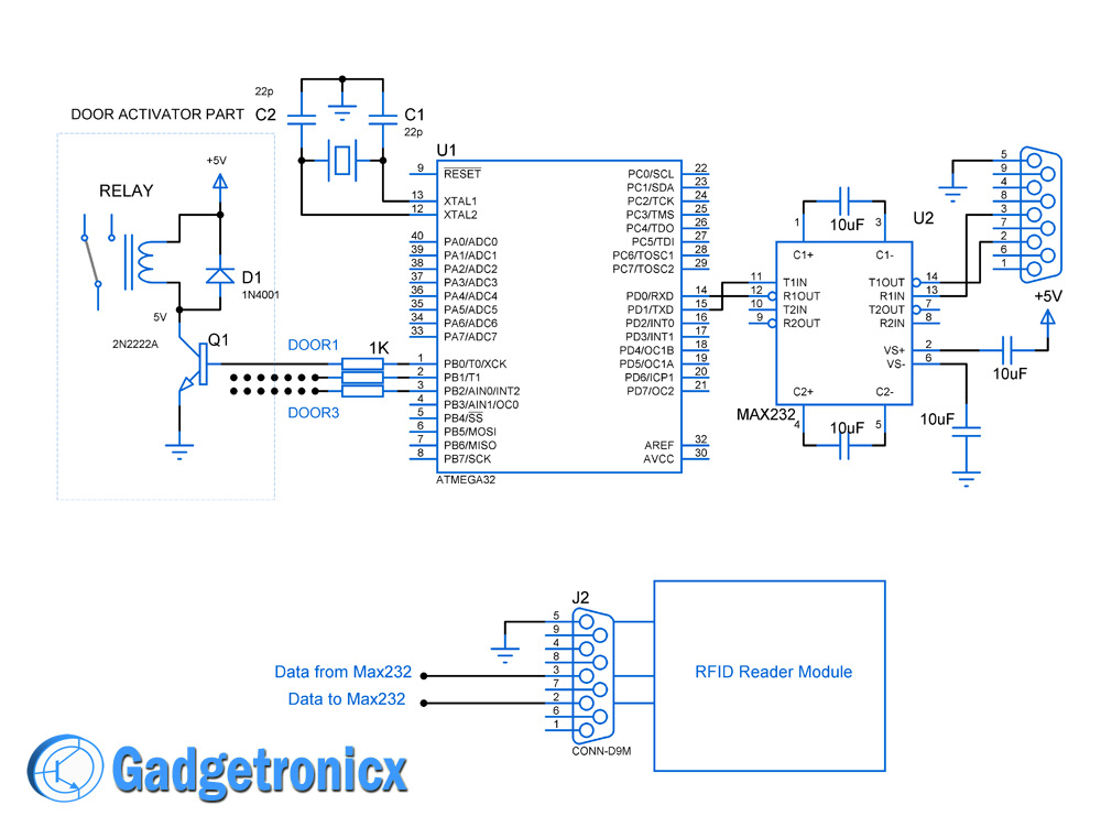 Three Relays must be connected to the PORTB for activation of the doors, for simplicity of the schematic design only one relay was shown in the above diagram. You can ignore the MAX232 if you obtain data as TTL logic in RFID reader.
SCENARIO:
In this project school level security scenario was chosen to explain the working of this system. Here Each tags will allow you to through a corresponding security level. For example a professor (MASTER TAG) have access to all the rooms and floors in a school whereas student (STUDENT TAG) only has access to classrooms and guest have access only to the lobby. Three Relays from PORTB was used as door activator for these rooms. .
I am having three RFID TAG namely “MASTER” “STUDENT” “GUEST”. When MASTER TAG was used RFID READER , all three relays gets activated (i.e professor access all rooms) , when STUDENT TAG was used only the relay to class room gets activated. Finally when Guest tag was used with RFID reader the relay to the lobby door only will get activated.
ALGORITHM:
- Initialize UART communication in the controller.
- Initialize scanning for any tags through RFID reader.
- Read the 12 byte RFID ID one by one through UART when any tag is placed.
- Match the ID with the existing records and seek for the security level of the corresponding ID.
- Activate the relay/door based on the security level.
- Wait for five seconds and deactivate the relay to prevent tail gating.
COMPONENTS USED:
- AVR Atmega32 microcontroller
- RFID reader module
- RFID TAG
- LCD module
- MAX232 circuit
- Jumper wires
For more detail: RFID based security system using AVR ATmega32 microcontroller